 Jacob Hahn
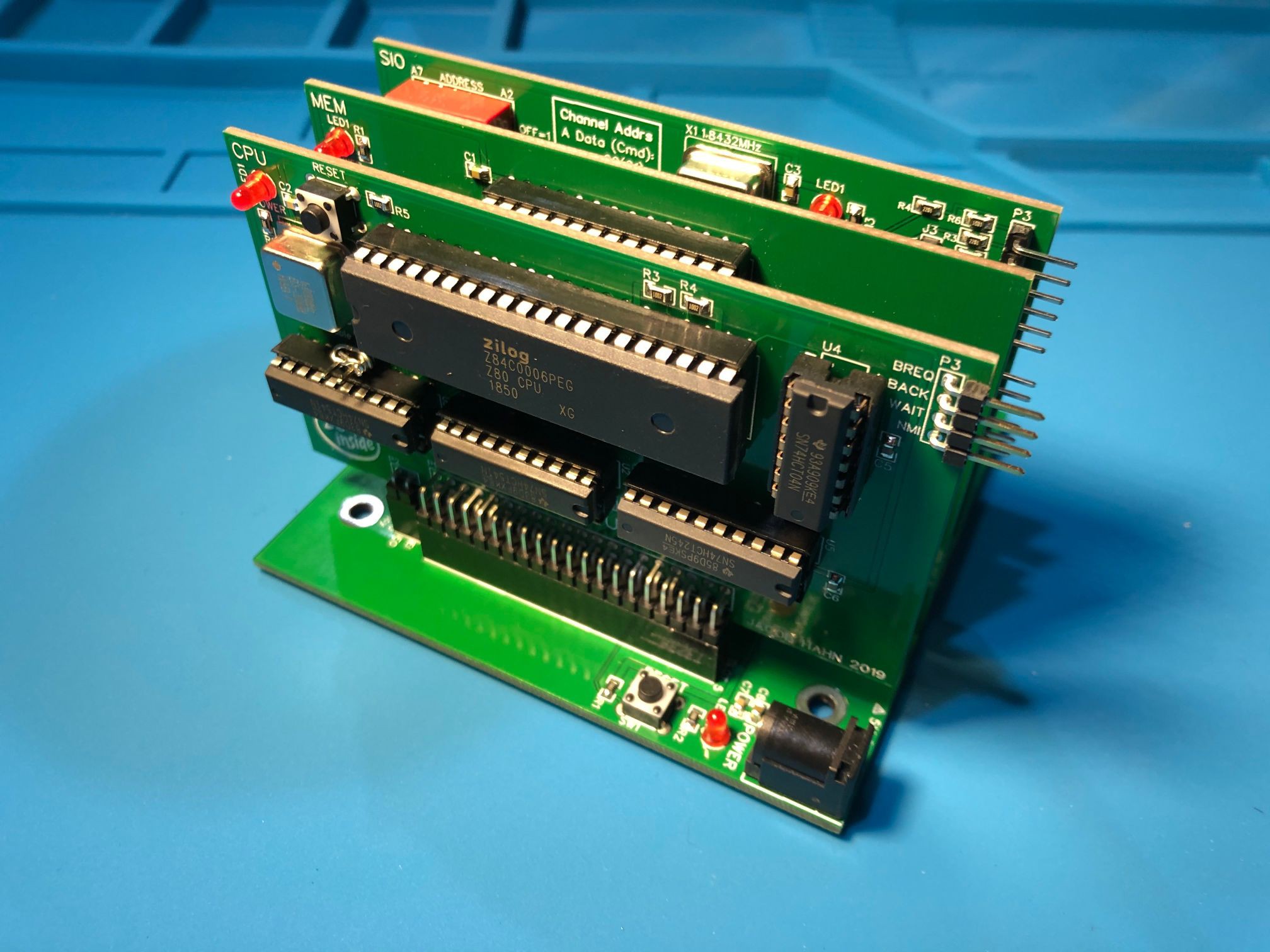
It's been quite a while since I've last posted, so I thought I'd update on what's been happening in the meantime. I've been working hard on the modular ZTO-80 design, and finally ordered the boards. I changed the pinout of the bus multiple times, finally landing on a version that keeps efficient trace routing for both the Z80 CPU and other peripherals. To keep things as simple and expandable as possible, I split the CPU and memory into their own modules. Currently, then, I have created a backplane, CPU card, 64K memory card, SIO card, PIO card, and a front panel board. The CTC card has not been designed yet.
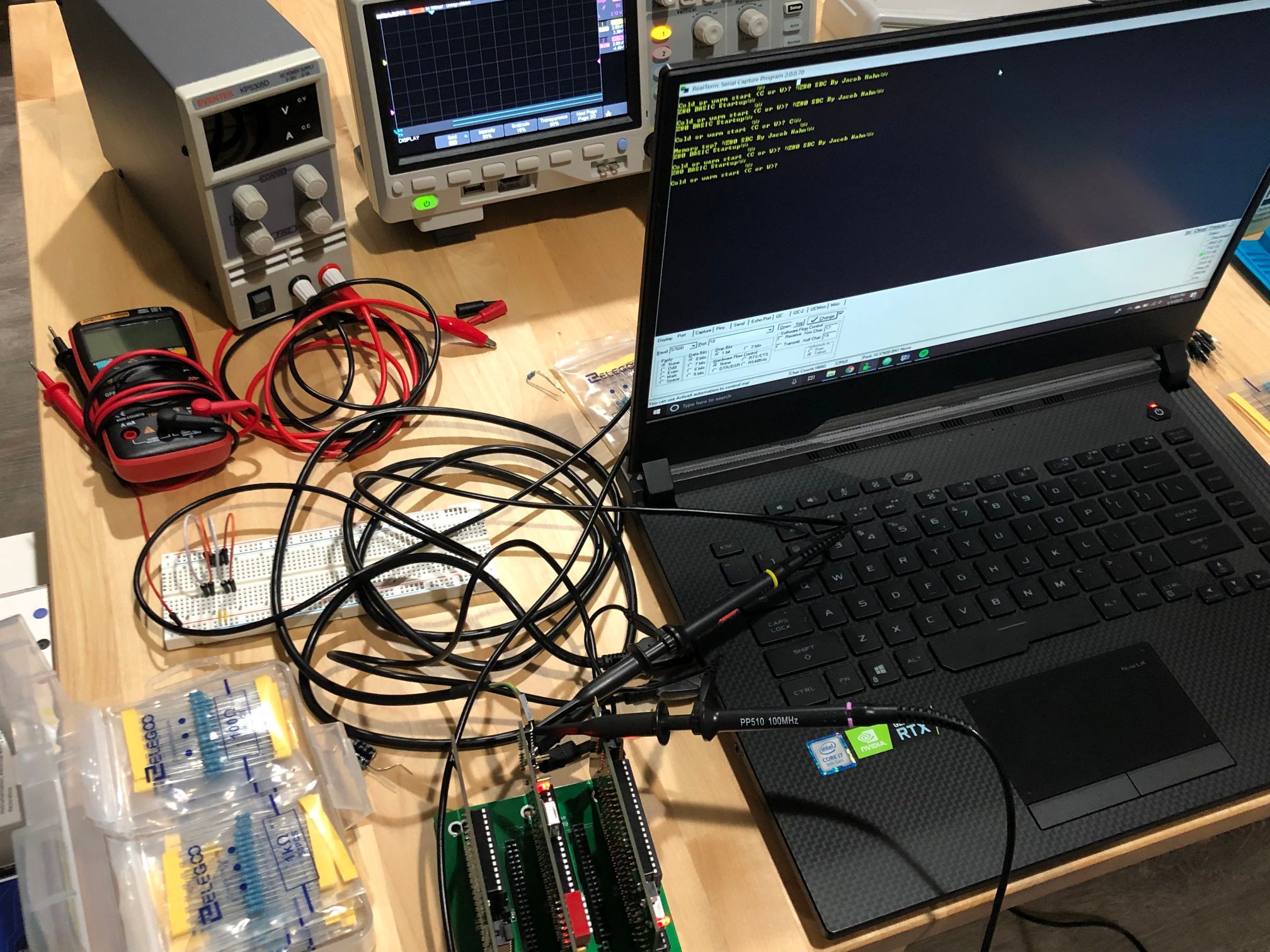
So far, I have soldered and tested a minimal system, using the CPU, memory, and SIO. After changing the address of my SIO in code, I booted basic to find that it worked. However, the computer refuses to respond to input after a single character has been sent until it is reset. I verified this issue using an oscilloscope on the SIO's port A RX and TX lines. Port A was connected to my computer. Using the decode function of my scope, I found that the data was being sent and received intact. This whole issue is confusing, as the code is exactly the same as what has worked on the SBC, with only an address changed. I'll have to keep looking around the system for problems and to check if it's software or hardware. Does anyone have any idea what could be causing this? I'm sure the front panel will be super useful as a troubleshooting device!
Here are detailed descriptions of each module of the ZTO-80 Bus System:
Backplane: The most important part of the system. The backplane I have designed contains 5 ZTO-80 Bus slots spaced .4" apart. Besides the slots, it has a standard jack for 5V power, smoothing capacitors, a power LED, a reset switch, and the slot pinout on the back. You could design your own backplane with more slots (if you keep the same board height of 3.9"), but 5 was the most I could fit without the width exceeding 100mm, which would raise the price.
CPU: The heart of the system. The bus was designed around the Z80, so that's what I'm using. The other major features are 74HCT buffered address and data lines to accomodate a TTL or CMOS Z80 and lots of modules, a breakout pin header for useful lines not included in the bus (I may add HLT to this in the future - I overlooked it!), and a slot for a system clock for whichever speed CPU you choose with a clock enable header.
Memory: The most basic card. It contains 3 ICs, specifically the RAM, ROM and an address decoder. The max memory supported is 64K, but a card with bank switching could add more.
SIO: This serial I/O card is used to communicate with a serial terminal, PC, or other serial device by means of a Z80 SIO/0 or DART (careful with the DART - it's a TTL chip in a CMOS system). There are two serial ports, with port B optionally connected to the TX/RX pins of the bus. The baud clock is included on the board. There is also a new address decoding system, utilizing an 8-bit magnitude comparator to allow for a total of 64 unique, tightly-decoded I/O addresses, programmable by a DIP switch.
PIO: A simple card based on the Z80 PIO. The design is exactly the same as the SBC, with two 10-pin headers for the channel outputs. Channel B includes a darlington transistor array for a max current of 500mA per pin. The module uses the same address decoding system as the SIO.
Front Panel: The earliest "personal computers", which used a 100-pin bus called S-100, had control panels on them to both monitor and manipulate the address bus, data bus, and control signals. I have designed a similar board for my bus which shows the address and data buses and some control signals using LEDs. At 6 MHz, the board is essentially useless, so I also implemented an instruction single step circuit that makes use of the WAIT control line to allow instructions to be run one at a time using a pushbutton, all without stopping the system clock. This feature can be enabled or disabled using a slide switch.
Discussions
Become a Hackaday.io Member
Create an account to leave a comment. Already have an account? Log In.