 Victor Dedios
Finally, we got to the last part. Yes, I decided to go for a hardware solution and stood for two different options: USB or Bluetooth: both of them presented benefits and disadvantages. I finally decided to go for USB due to its simplicity on hardware and the fact that it didn't need a battery.
I also decided to update the design adding more buttons from the original design to be able to play more systems. I was increasing capabilities with this and standing for the principles I was pursuing since the beginning: creating something durable and versatile, taking most of the resources I had.
Now, let me explain you what was the final result of the designs I made:
HARDWARE
As explained, playloop connects to smartphones through USB port. It uses USB standard to communicate and, when connected presents itself as an HID device. To achieve this it mounts a AVR Atmega328p. Wait a moment, did you mention Atmega328p and USB-HID? Yes, in the software side, it runs on V-USB firmware. It is a firmware-only USB driver for AVR microcontrollers published under the terms of the GNU General Public License Version 2 (GPL). It enables a few of microcontrollers in AVR family to present themselves as HID devices. Once you plug Playloop into your smartphone, its a matter of opening a compatible emulator with gamepad recognition like, for example, RetroArch and start playing! It is compatible with Android devices, and it can run with MicroUSB or USB-C. I haven't work yet on iPhone models because Apple has restrictive policies about emulators and, since I wanted to turn this into a real product, I decided to reach a smaller goal being more focused.
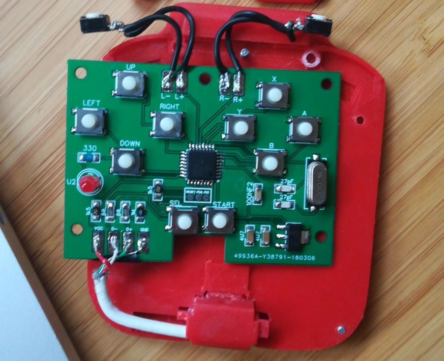
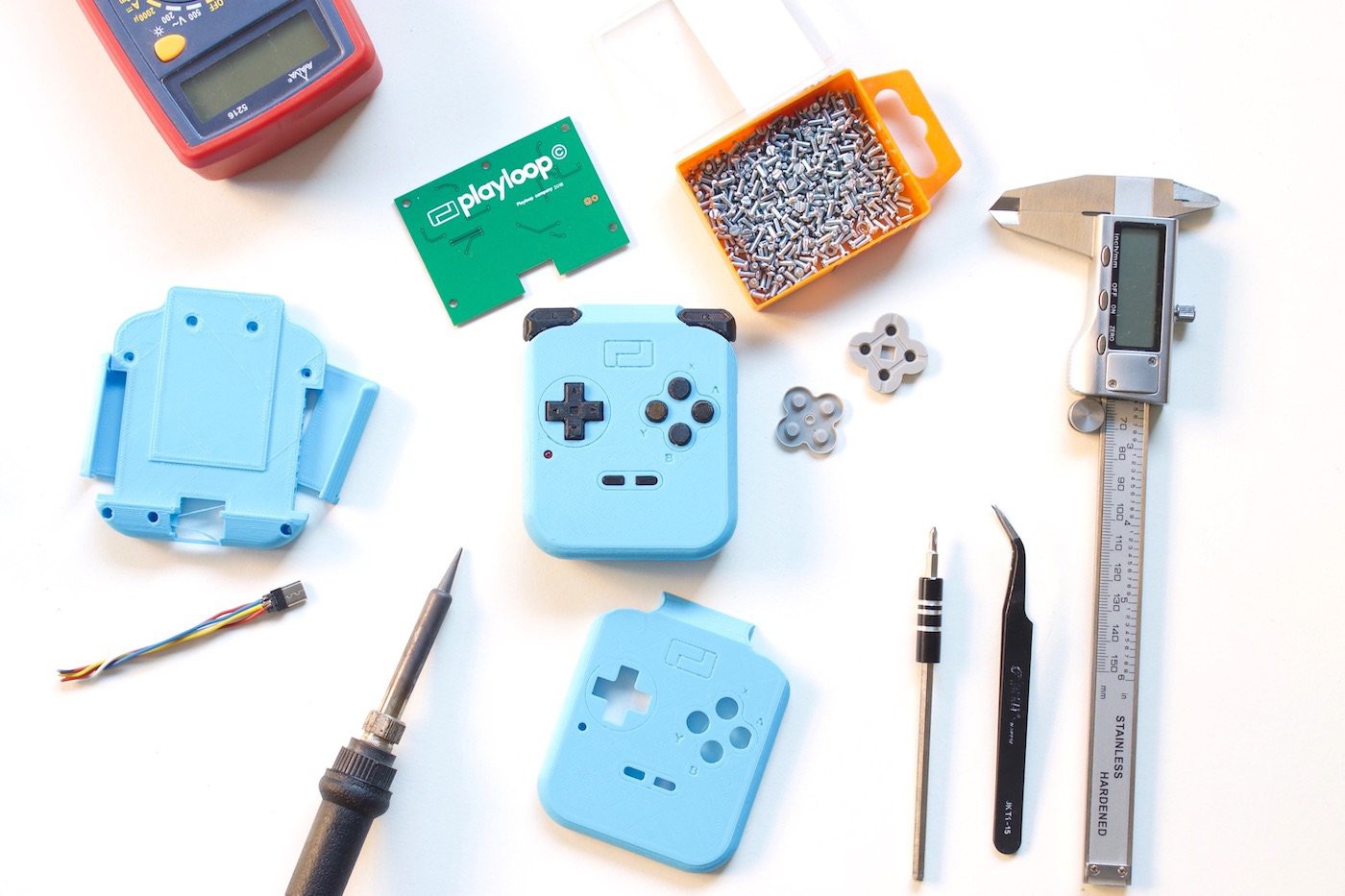
This is an earlier version o the board, it mounts tactile switches. The final version uses Nintendo ds lite rubber pads for a better performance
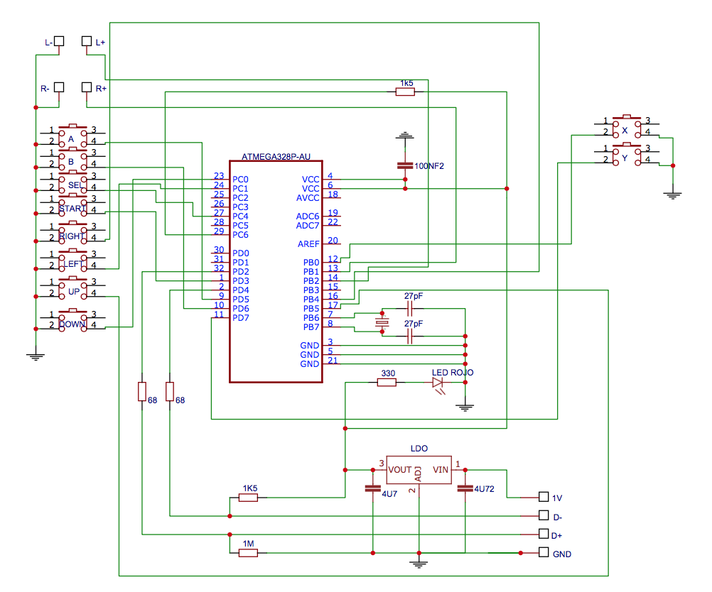
The design of the board itself is pretty straight forward. Every pad is an open switch which, once closed, connects a certain microcontroller pin to ground. The rest of components are capacitors, resistors, LDO regulator, led and cristal clock needed for the microcontroller to properly work. We could say that it is like an Arduino specially prepared for acting as a gamepad. Here you can see the schematics:
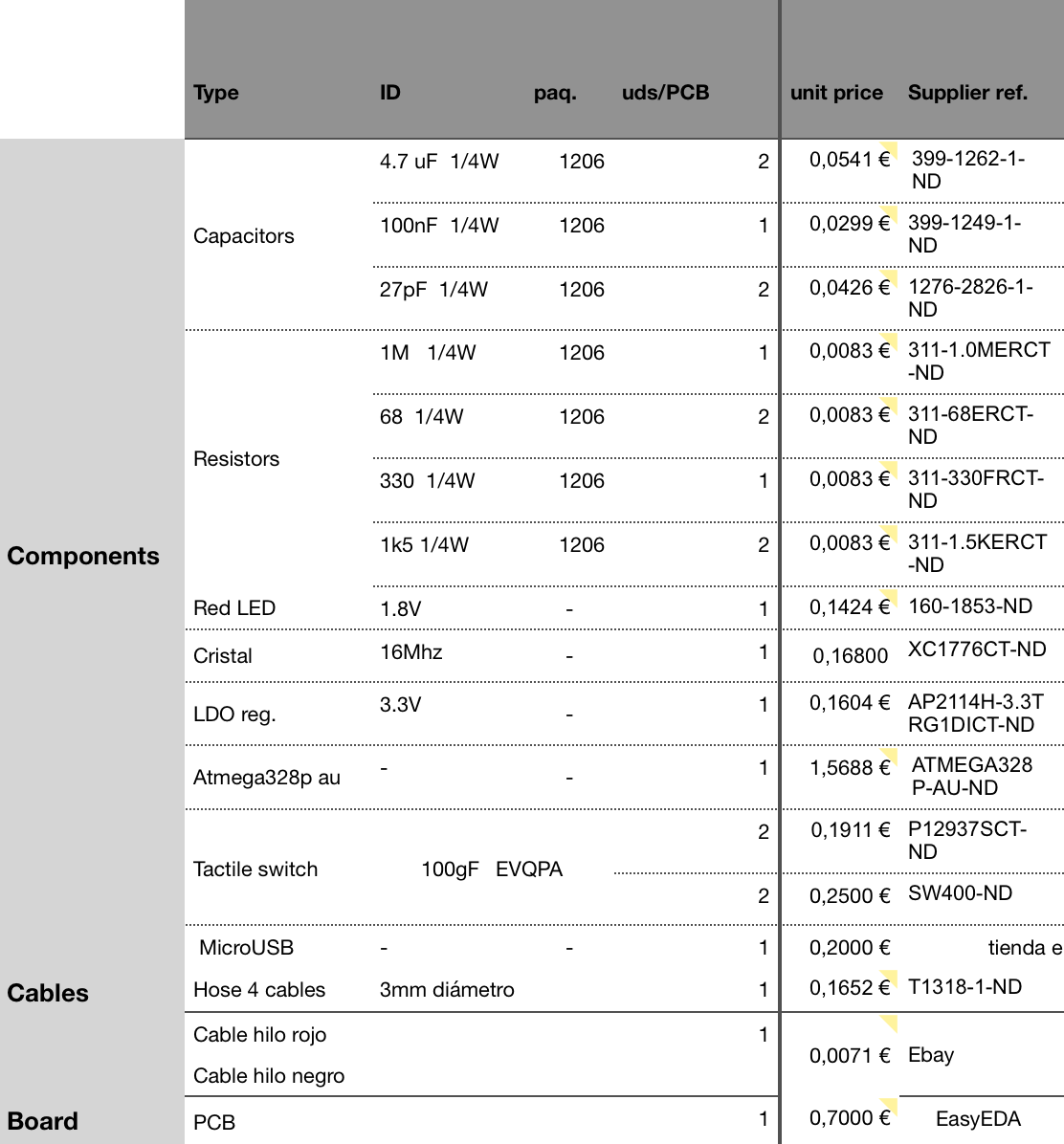
Here is a BOM for the componentes used:
SOFTWARE
On the software side the thing gets a little bit trickier. Once the signal is received (pin is been set up to GND) the microcontroller adds the pin's state to an array which, once all the USB initial communications have started, is sent as an update of required polls by the master (the smartphone). Then the smartphone, due to the HID communication standard, translates this states and makes Super Mario jump ;)
One thing I haven't said is smartphones need to be OTG to be able to use Playloop. This is a USB standard which enables smartphones to communicate in both directions, in and out the phone (in could be for example charging, out could be storing data on a external pendrive)
You can find in the files side the .hex code. I will be updating the full code in the next days.
MECHANICS
Ok, cool, but how it holds on my smartphone? Does it fit on any phone size?
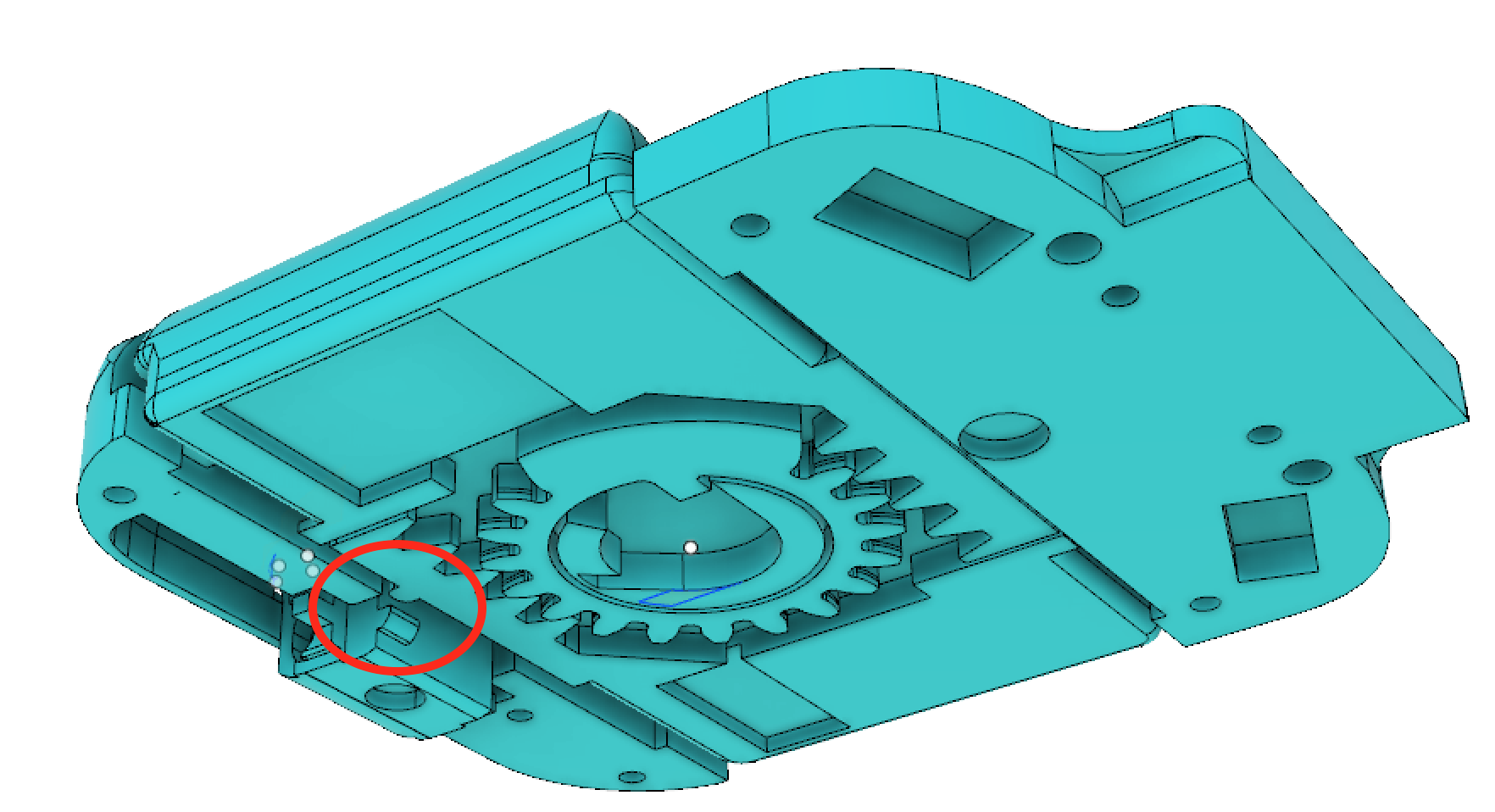
Yes, it is adaptive to almost all smartphones of the market and it holds pretty well. It is has two wings that expand up to 84mm wide. When they do so, they are driven by an internal gear and a linear rack that ensures a regular movement. This gear mounts inside a torsion spring which holds the wings on the smartphone. To ensures that Playloop is correctly attached, this two wings has a tiny rubber material called nano suction tape which prevents it to fall.
As you can observe, USB pin is initially hidden but, when sides are opened, it expands. This is due to a small mechanical lock that it has inside. This lock frees the USB pin when sides are opened, and a internal spring that it has pushes it outside its cavity.
To clarify, this is not the first version I designed, in fact it could be iteration 5-6. The first working prototype had all the back cover, the one that is in contact with the screen, covered with nano suction tape. The problem was that it held on the phone pretty well for the first 10 minutes but, after that it started to lose adhesion. So I decided to change the design and go for a lateral opening solution.
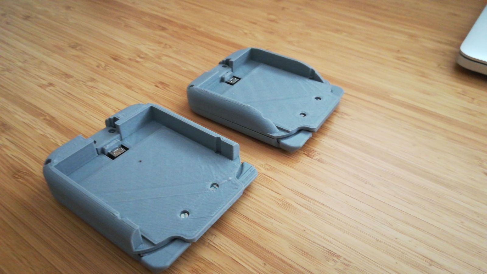
This are some physical models I printed to test how I would feel to have the wings.
MANUFACTURING
Due to financial constrains and, after thinking about it a lot, I decided to go for 3D printing when manufacturing parts. Despite the decrease on quality it will suffer from, it was the most realistic way to go for my situation. With this choice I could have a more flexible production (having in mind that I was not going to get a lot of orders at first and just wanted to test market) and, of course, it was cheaper. I wanted to gather attention from very enthusiastic customers that could forgave the fact of being 3d printed, you know: family, friends and fools.
Ok, Playloop is fully 3D printed, but this does not mean that was designed without having DFM in mind for scaling on manufacturing in the future. It is designed in such a way that most of the parts would require little adjustments to be injection molded. Its assembly is easy, excepting a few steps that have to be improved, it is just a matter of putting some parts together and tighten screws.
So the manufacturing process ended up being, briefly:
- 3d print parts
- Order PCBs to Chinese manufacturer and electronic components
- Hand solder PCBs
- Assembly parts and PCB
It was tough to build and and assembly all the units by myself and I could have gotten into debt in order to make someone else build them for me. But I believe it is important to be patient, know where you are and which resources you have. Set up some borderlines and scale when you are ready. Do not be afraid to jump into the mud.
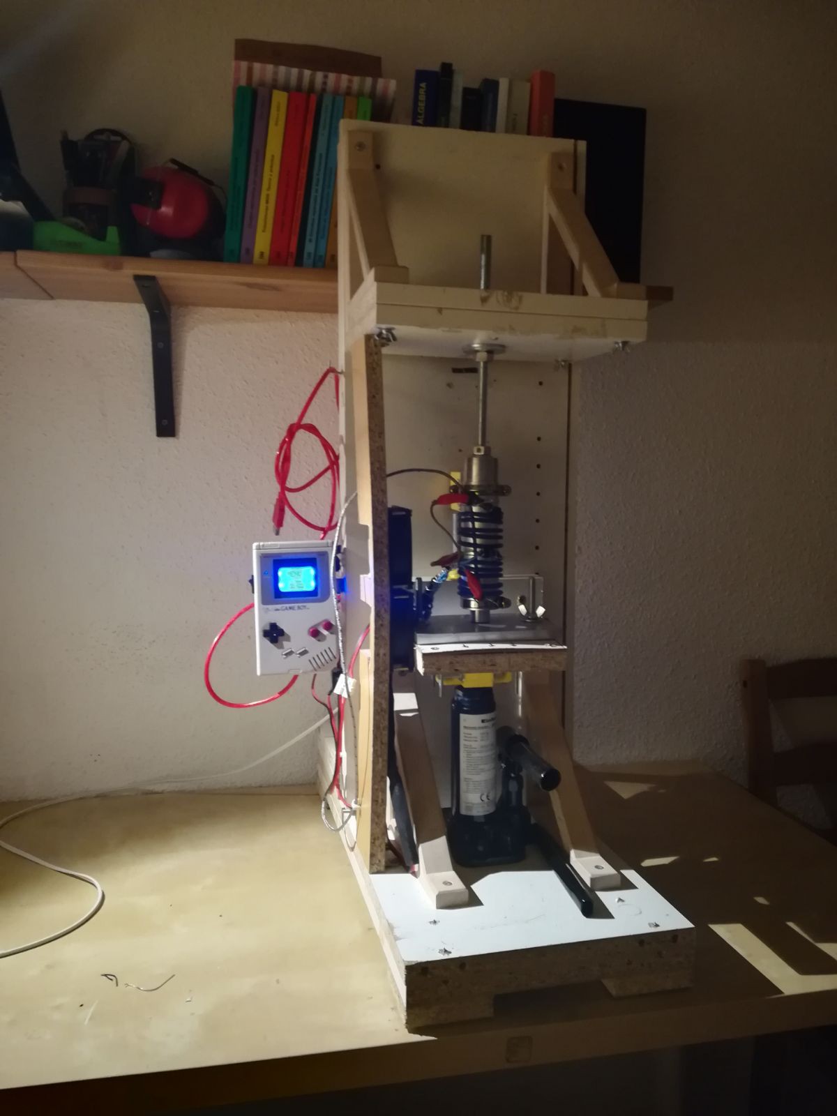
Just to finish, and as a funny story, I would like to share that I considered manufacturing some of the parts with injection molding by myself. I built kind of a "machine" with a hydraulic jack, an Arduino based PID controller, thermocouples, resistive heat thread and a solid wood structure based on IKEA furniture wastes which ended being more of a distraction than a useful tool. This may be an interesting topic for another project, but since it didn't work at all, let's pause it for now and keep it like this.
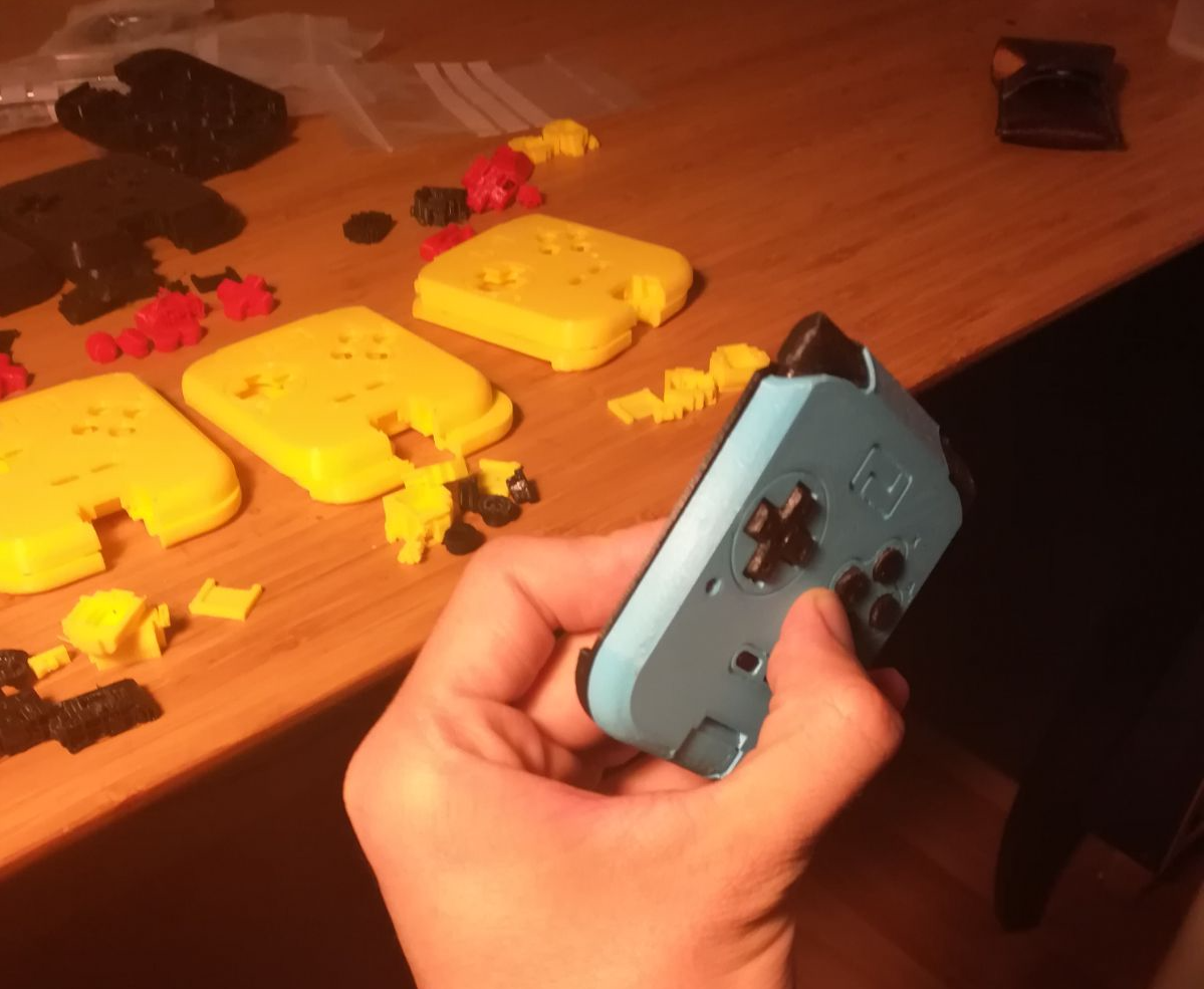
Note how cool looked the GameBoy shell as a controller. Do not worry, it was just a clone one i had laying around ;)
Discussions
Become a Hackaday.io Member
Create an account to leave a comment. Already have an account? Log In.