 Duane Degn
console-beaverThe hit detector enclosures are held together with friction only. I think it's hard to open a hit detector without marring the plastic. I personally would rather take something apart rather than keep it pristine. Here are some photos of the open hit detector.
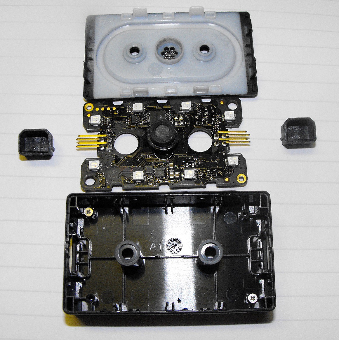
The PCB is held in place with two screws. I replaced the screw in the enclosure to reduce the chance I'd lose them.
Here's a photo of the top of the PCB.
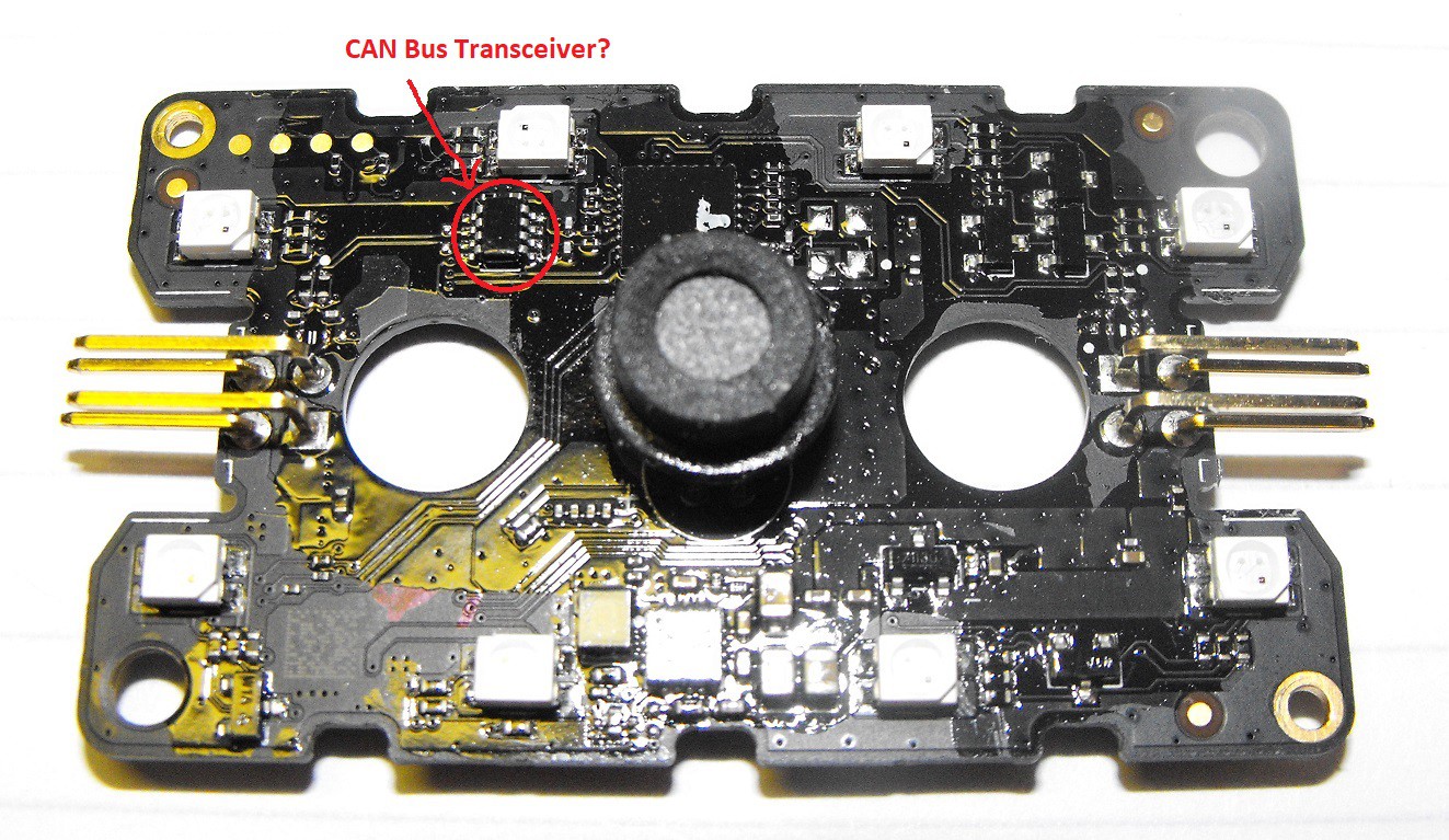
The PCB has a conformal coating. I think there are three resistors next to each of the eight LEDs. This makes me think the LEDs are not the individually addressable sort. I think all the LEDs in one hit detector have to have the same color combination. It appears hit detection is done with sound.
The 8-pin chip at the microphone's 10 o'clock position is likely a CAN bus transceiver. I think it converts between CAN Bus differential signals and signals the on board microcontroller can use.
Here's a photo of the bottom of the PCB.
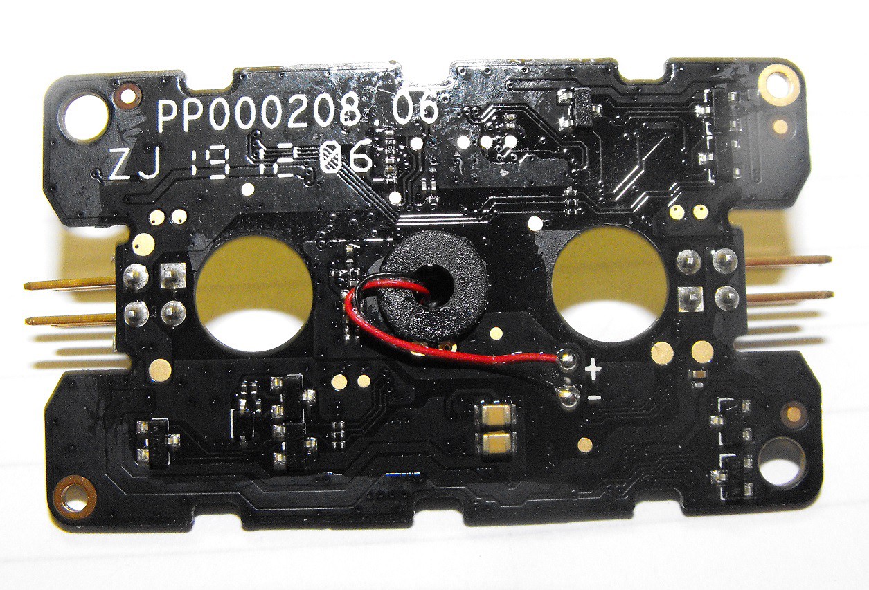
I was surprised to see the microphone connected with wires.
The conformal coating makes reading chip labels extra difficult. I scrapped the coating off the largest chip and took a photo.
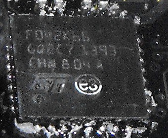
If anyone figures out which chip it is, I hope they let me know. I may attempt to get better photos with a microscope and using a different hit detector. Maybe I can read the text better with the coating in place by using a light at a proper angle.
Edit: As pointed out by console-beaver and postart168 the chip is a STM32F042K6 ARM Cortex-M0 MCU. postart168 even provided the datasheet page number to seeing the markings. Thanks to both of you.
Edit: I recall why I didn't initially think this was the Arm chip identified above. According to page 26 of the datasheet, the CAN bus is good up to 1Mbps. The CAN on the Robomaster S1 is 2Mbps according to multiple traces I've captured using a Saleae Logic Analyzer. There a logic analyzer file included in the file section of this project.
Discussions
Become a Hackaday.io Member
Create an account to leave a comment. Already have an account? Log In.
The SOIC-8 packaged chip could be a can bus transceiver as you noticed, however there're plenty of different chips available in SOIC-8 package, it's hard to say which one is this without seeing the markings.
Can you try to carefully scratch conformal coating off this chip and try to take a good picture of the marking so we can try to id it?
Are you sure? yes | no
The MCU chip on a hit plate looks like stm32f042k6?
https://www.st.com/en/microcontrollers-microprocessors/stm32f042k6.html
Are you sure? yes | no
It looks like you are correct. The matching markings are showing on page 104.
Are you sure? yes | no