 Duane Degn
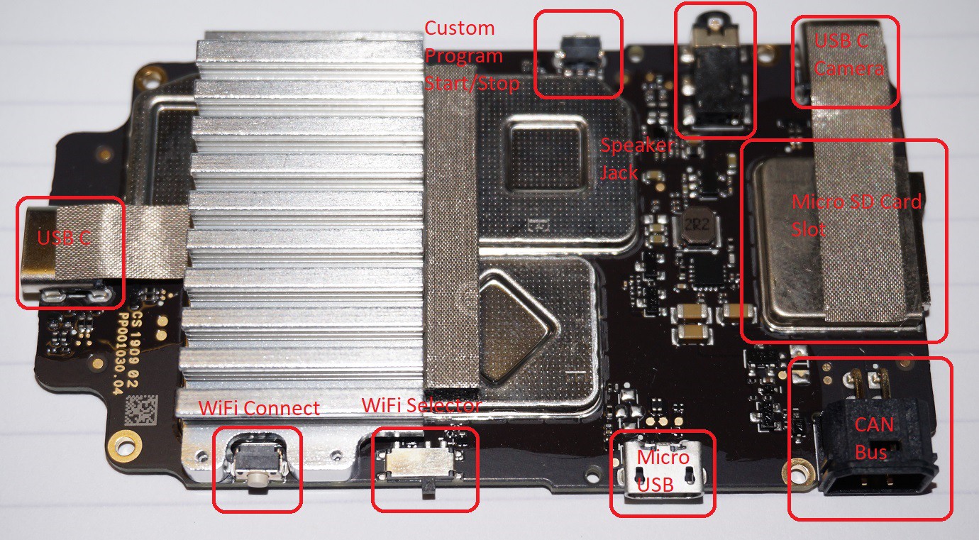
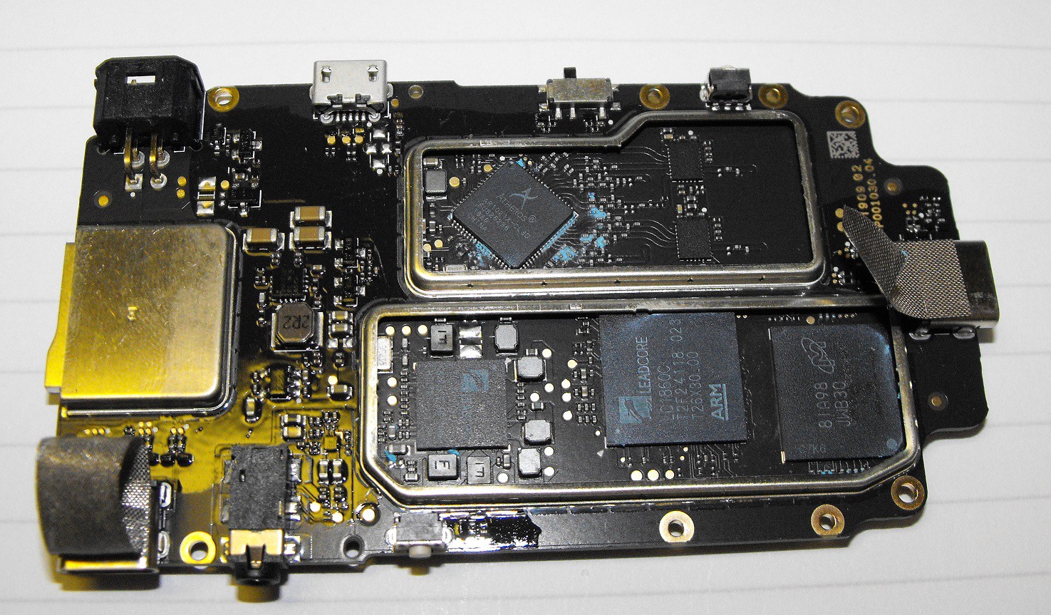
I've opened up the Intelligent Controller. This is the small computer which sits at the top of the S1's turret. The Intelligent Controller has three USB C type connectors. One of these connectors is used with the camera. I don't know how the other to USB C connectors are intended to be used. It's possible one could be a video display connection and one could allow a keyboard and mouse connection but these are guesses on my part.
The Intelligent Controller also has a micro SD card slot at its front. According to the documentation, it can accept SD cards up to 64 GB.
Opening the enclosure is relatively easy. I just used the tool which came with the S1 to remove the four hex screws.

Edit: I had previously incorrectly labelled the Micro USB connector as a USB C connector. The above photo shows the corrected label.
There I two WiFi antennas which connect under the black square of tape.
The PCB is held in place with four stainless steel Phillips head screws. Four black Phillips screws hold the heat sink to the board.
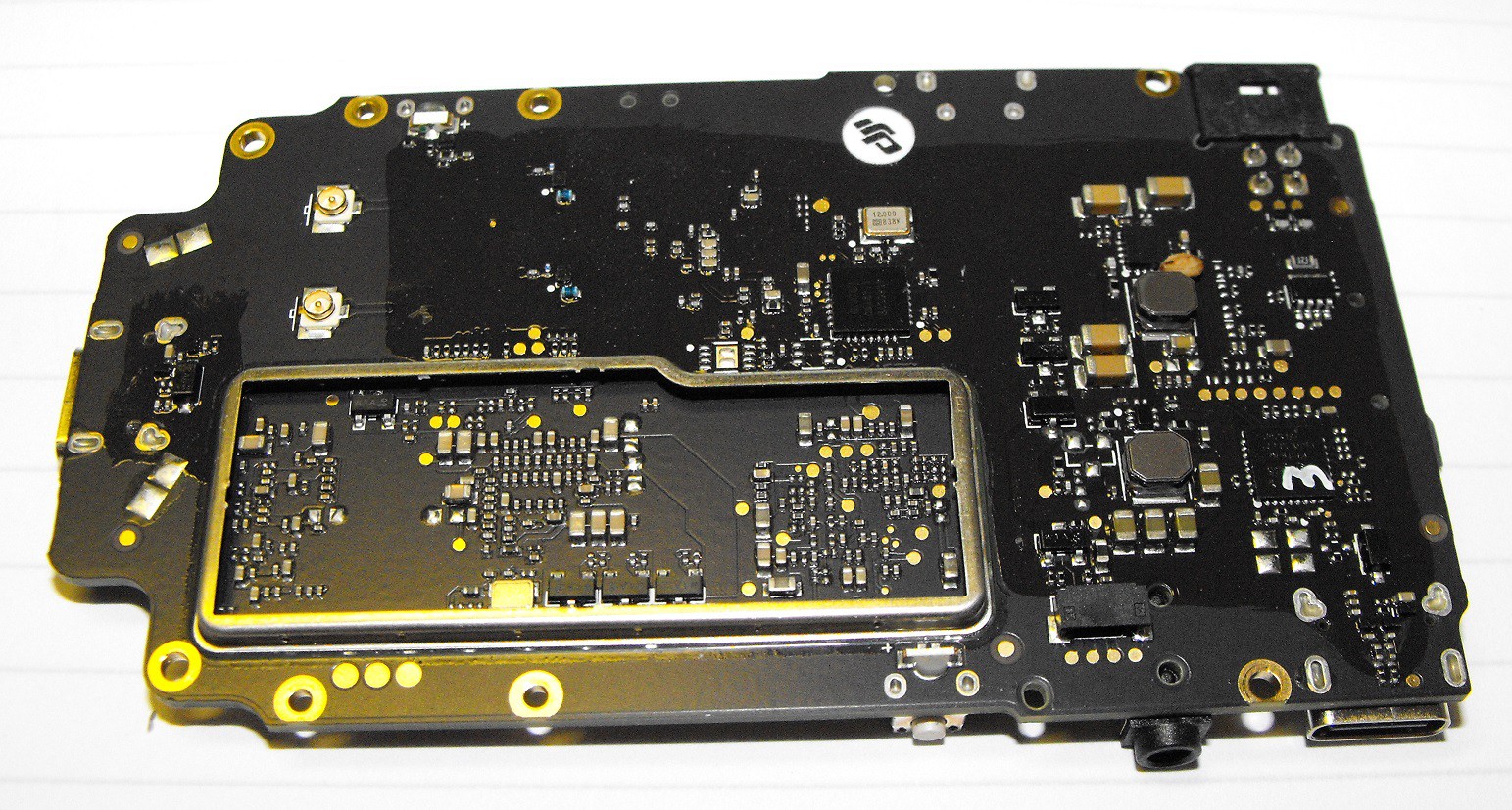
A removable metal shield covers an area of the PCB. There isn't anything very interesting under this shield. It looks like most of the parts under the shield are passive components. (Note the PCB was rotated 180 degrees between taking the photo above and the photo below. The two photos were taken with different cameras.)
The top of the PCB has two shielded areas. A heat sink partially covers both the shielded areas. There's a shield over the SD card slot but this shield is not removable.
Edit: I had previously used a photo which incorrectly labelled the Micro USB. The above photo should be correct.
There's a lot blue thermal paste between the heat sink and the top of the metal shields.
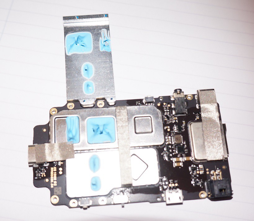
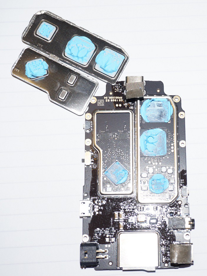
Like the metal shield on the bottom of the PCB, the metal shields on top of the PCB are also removable. More blue thermal paste sits between the shields and many of the chips being cooled.
I attempted to clean the chips in order to read their labels.
I wasn't able to read the label of the two chips without thermal paste. Here's the best photo of my attempts to capture the text on these chips.
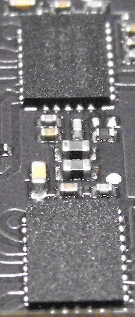
My initial guess was these were some sort of memory chips. I don't think they are memory chips though. Since they share the shielded area with a WiFi chip, my latest guess is they're used with the WiFi radio. Sorry I wasn't able to get a better image of the label.
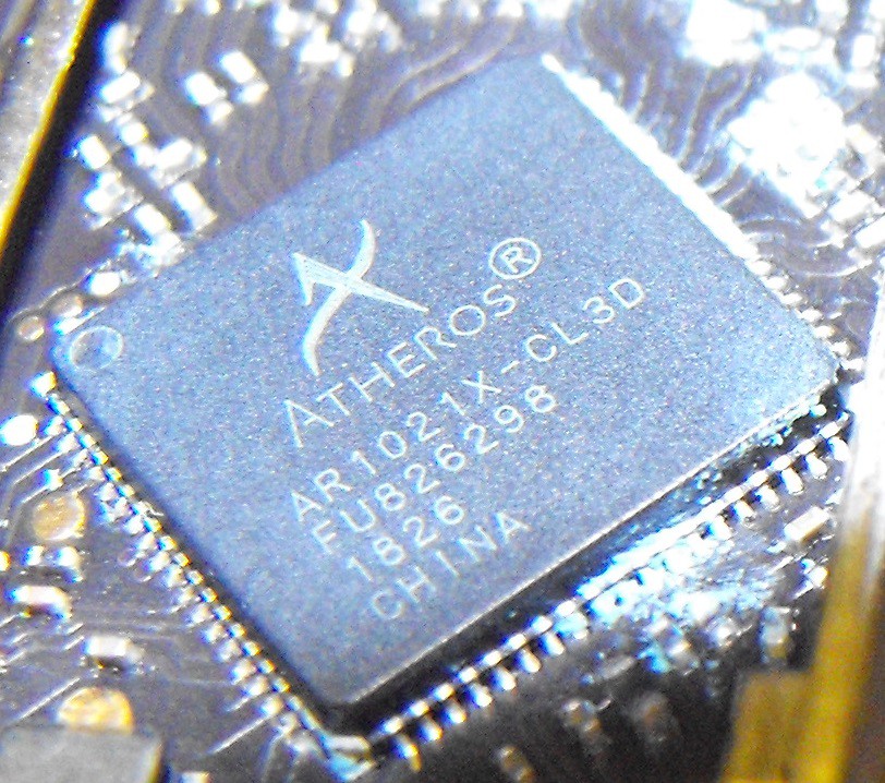
Here's a closeup of the nearby WiFi chip.
Below is a photo of the smallest of the three chips under the other metal shield.
A quick search suggests this is a power management chip which is also used in DJI's Mavic Pro.
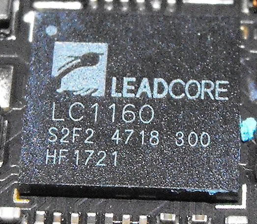
Next to the above chip is another Leadcore chip.
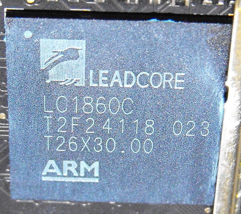
This is obviously an "ARM" processor of some sort. My initial search suggests this is a dual-core 32-bit processor with a modem. One document states its max clock frequency is 1200 MHz. I'm guessing this is the main "brain" of the board and robot.
Edit (September 6, 2019): As Bruno Albuquerque pointed on in a comment, the LC1860C us a quad-core processor. It runs at 1500 MHz. Thank you Bruno.
The third chip under this shielded area is shown below.
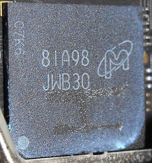
This is a Micron chip. I think the part number is MT29TZZZ4D4BKERL-125 W.94M.
I think this is an eMMC memory chip but I'm not sure about this.
Here's a photo of the inside of the enclosure without the PCB.
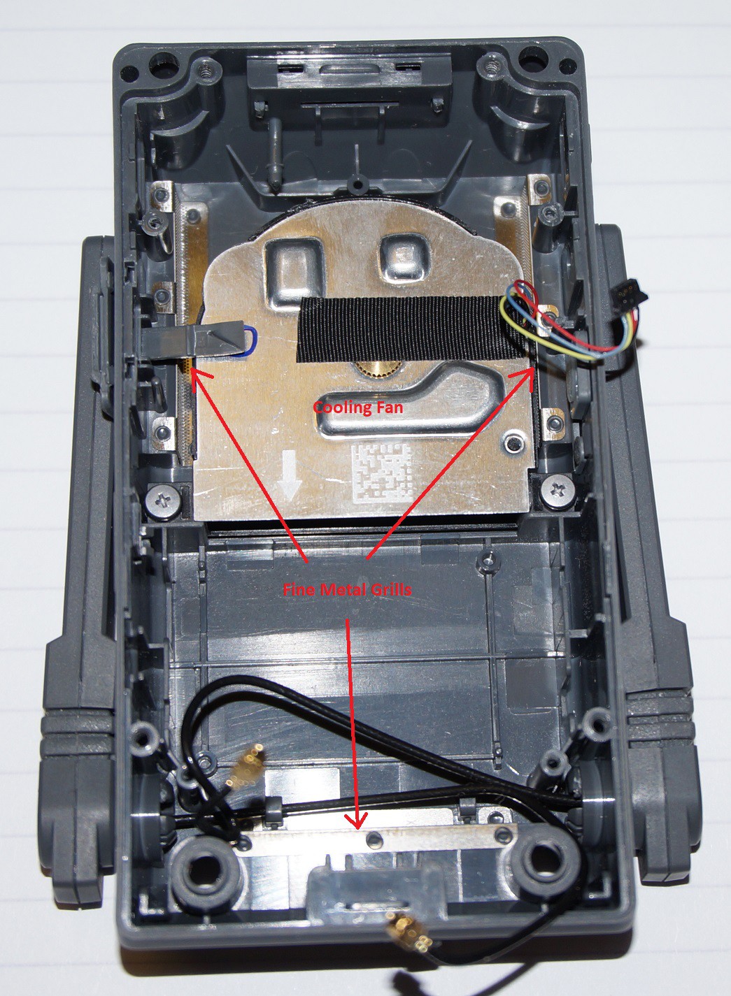
The fan pulls air in from the two sides, blows it through the heat sink and the air exits out the back. Both the intakes and exhaust opens are covered with thin metal with lots of very small holes which acts as a filter/dust barrier.
Edit(210330): Wardword reports on the DJI forum than the USB-C cable used with the camera appears to be unique to this device.
Discussions
Become a Hackaday.io Member
Create an account to leave a comment. Already have an account? Log In.