 Duane Degn
Notice: Removing the side panels will likely void your warranty. There are multiple types of tamper indicators. There are little white stickers and also little globes of glue in fastener heads. I personally think you don't own a product until you've voided the warranty.
The turret side panels are secured with 7 star (Torx?) type fasteners. The bit I used to remove these fasteners is labeled "T5." Two of the seven side fasteners are located under the dark red filter. These dark red filters are not easy to remove without marring the plastic.
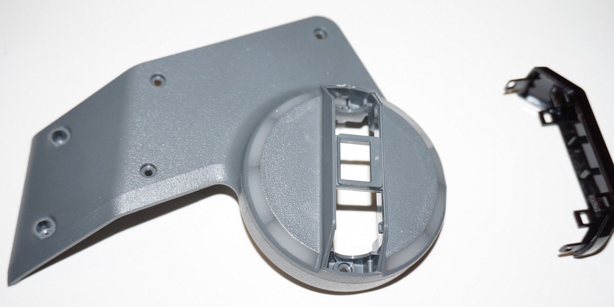
Once the seven fasteners are removed, the side panels may be pulled off without too much effort. The side panels will remain securely attached without use of the fasteners. Below is a photo of the inside of the right side panel. The left panel is a mirror image of the right panel.
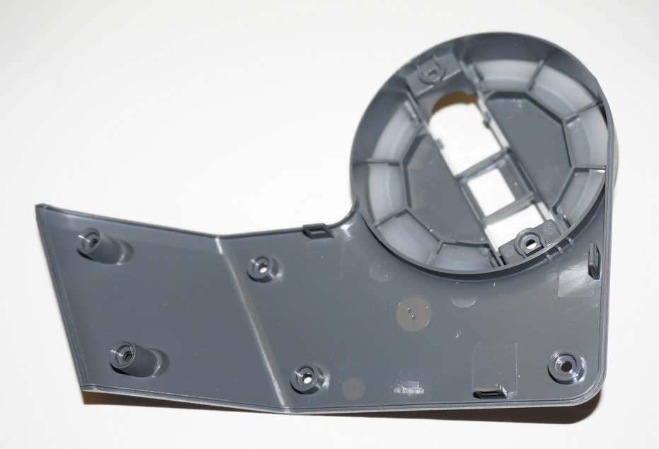
The white translucent material appears to be securely glued in place. I didn't see any obvious excess glue but the translucent plastic acts as if it's completely merged with grey plastic.
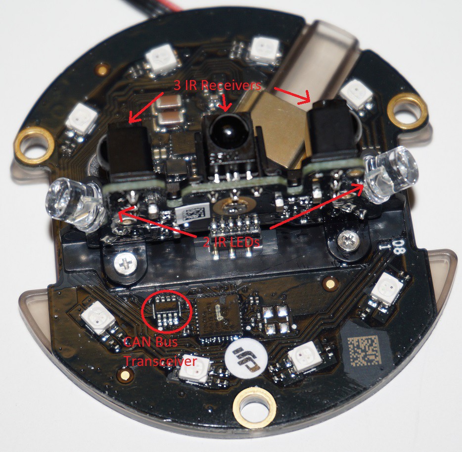
Each side contains a PCB with two IR transmitters and three IR receivers.
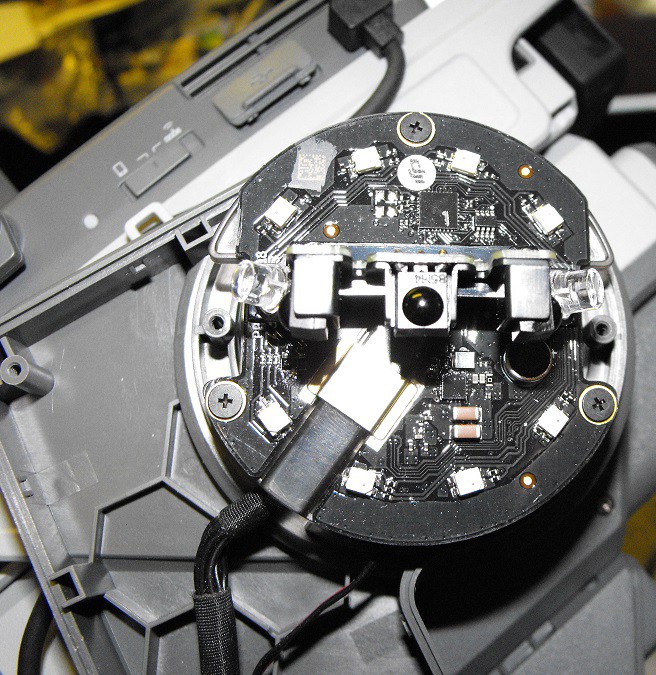
The PCB has a plastic plate on the bottom. Part of the purpose of this plastic plate is to allow a path for the tilt control wires on the right side.
The above photo shows the PCB upside down. The two stainless steel screws are self threading and hold the PCB to plastic support piece. If anyone reading this takes about their gimbal, be aware there are multiple screws which are very similar but use different threads.
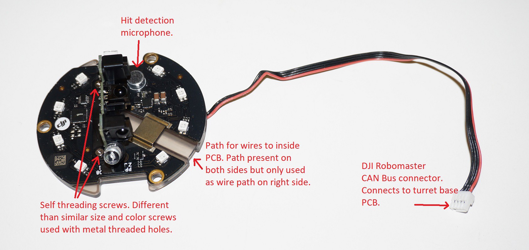
The left and right turret hit detector PCBs are not mirrored. The PCBs and plastic support piece are identical. The path for the tilt control wires on the right side, is oriented in such a way as to only work correctly on the right side of the turret.
The white CAN Bus connector is 0.05" (1.27mm) pitch. The four conductor ribbon connects to the back of the PCB at solder pads spaced 0.1" (2.54mm).
The two small stainless steel screws secure the IR receivers and IR LEDs to plastic support tray under the main PCB. A third small stainless steel screw secures the daughter PCB to the black plastic shields.
Here's a photo of the bottom of the PCB.

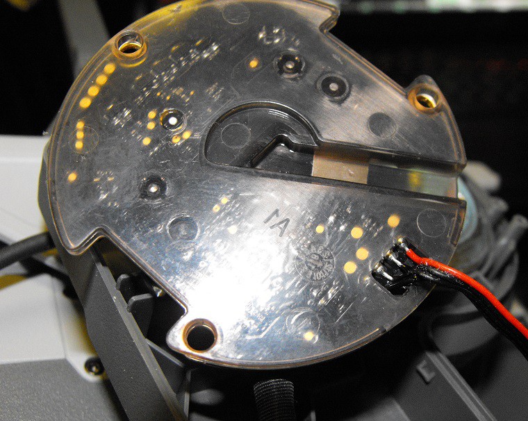
Above shows the plastic support still attached to the PCB.
Above shows the PCB side of the plastic support.
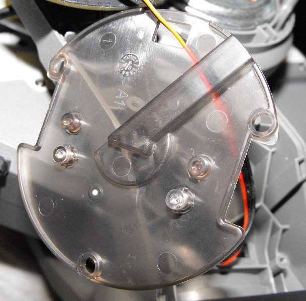
Without the plastic support the route of the tilt control cables is easier to see.
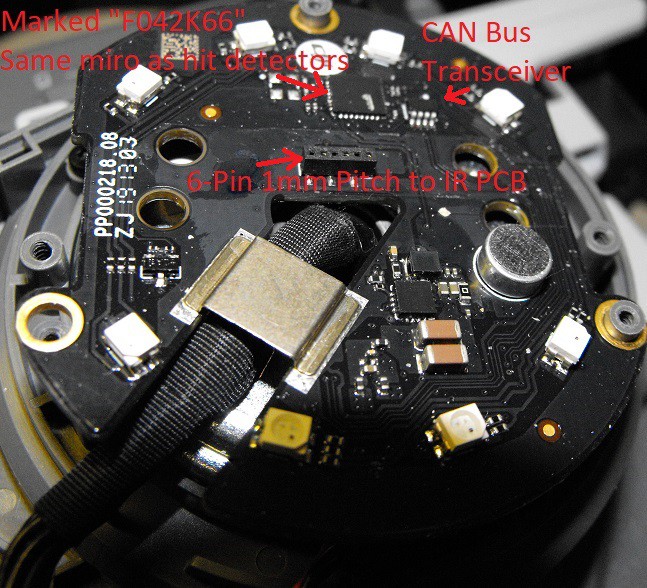
The turret hit detectors apparently use the same microcontroller as the main body's hit detectors.
The left and right turret hit detector PCBs are nearly identical. The only difference I've found is in the last four digits of the text printed on the board. The text on the right PCB ends with "19 1303" while the text on the left PCB ends with "19 0801."
As I noted on on the photo, the IR daughter board connects with a 6-Pin 1mm pitch header.
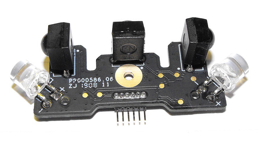
As you can see the right IR PCB has text ending with "1908 11." The left IR PCB has text ending with "1919 09."
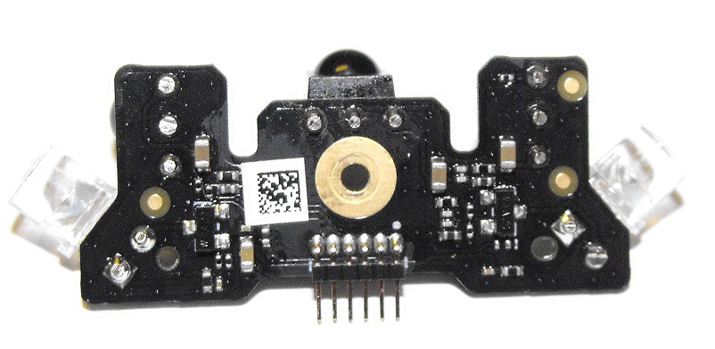
The IR LEDs are not directly driven from the microcontroller. There are transistors which are connected to the anodes of the IR LEDs. Based on the number of pins and the number of components on the daughter board, I suspect the LEDs are controlled in parallel.
Discussions
Become a Hackaday.io Member
Create an account to leave a comment. Already have an account? Log In.