 Duane Degn
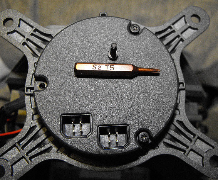
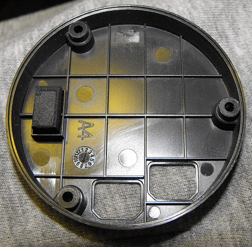
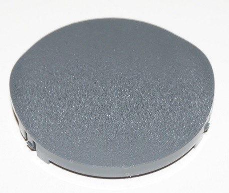
The cover of the base is held in place with three T5 Torx head fasteners.
The two black CAN bus connectors are used to allow more current to pass to the turret. The turret uses a lot of the S1's power. The Intelligent Controller, gun, and brushless motors all are relatively power hungry devices.
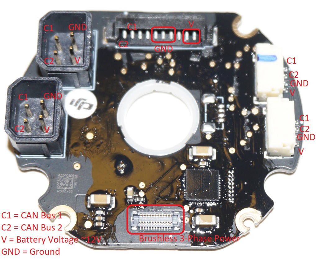
Besides the two 4-pin black CAN Bus connectors, there are three other CAN Bus connectors on the turret's base PCB. I figured out the purpose of five of the ten positions of the black 10-pin connector. The ten wire cable passes up the right side of the turret to the turret's tilt controller. There are two four wire CAN Bus cables which connect the turret's hit detectors to the base PCB. The connector marked with blue ink is used to connect the left turret hit detector.
The large square chip near the brushless motor connector is likely the brushless motor controller. After I scrapped the coating off the chip, I was able to a couple good photos of the markings.
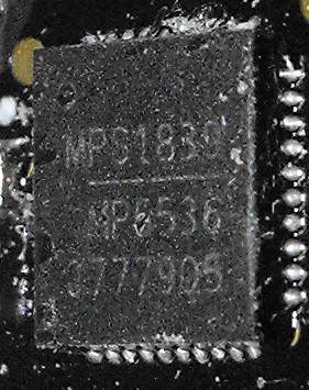
I'm pretty sure the top line is MPS1839 and the second line is MP6536. Here's a photo from a different angle.
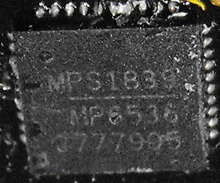
I think the second line is easier to read in the above photo than the first one I posted. I haven't been able to figure out which parts these are. I'll edit this log if someone is able to identify this chip.
Edit: Thanks to Bruno Albuquerque for finding a datasheet for the MP6536 chip.
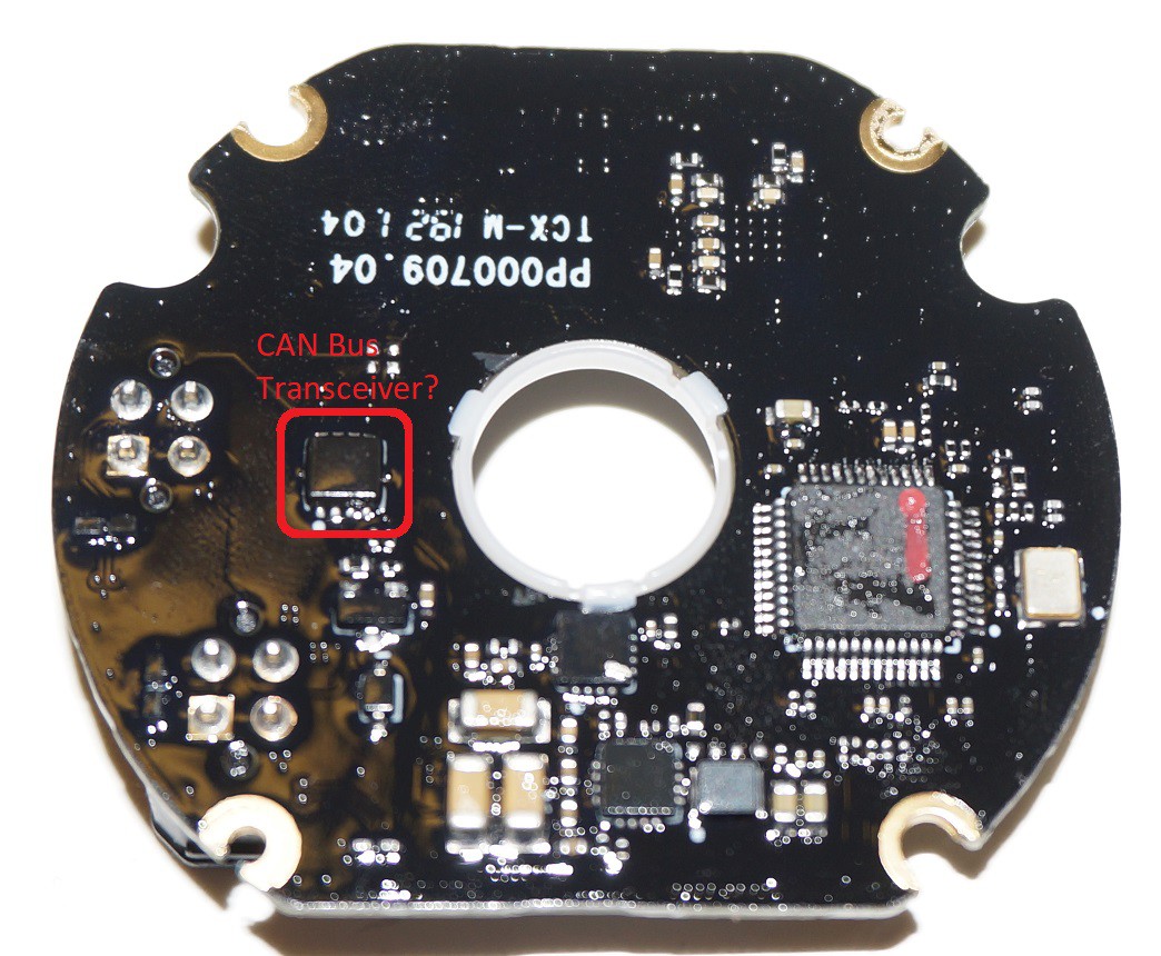
The conformal coating makes identifying chips difficult. I believe the largest chip in the photo above is the microcontroller for this board.
Edit: The microcontroller chip has the following markings:
Top Line: GD32F 33G
2nd Line: C8T6
3rd Line: BK52KQ
4th Line: JJ1831
Bottom Line: Some sort of logo and the text "ARM"
The main reason I suspect the highlighted chip is a CAN Bus transceiver is the 8-pin SON-8 package. So far the other CAN Bus transceivers appear to each have 8 pins. This may be the SN65HVD75DRBR RS-485 transceiver chip which is also used on the Motion Controller board.
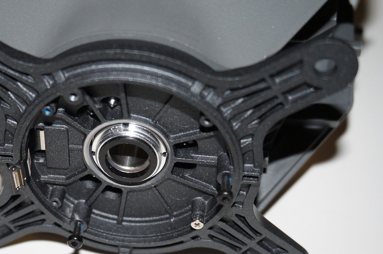
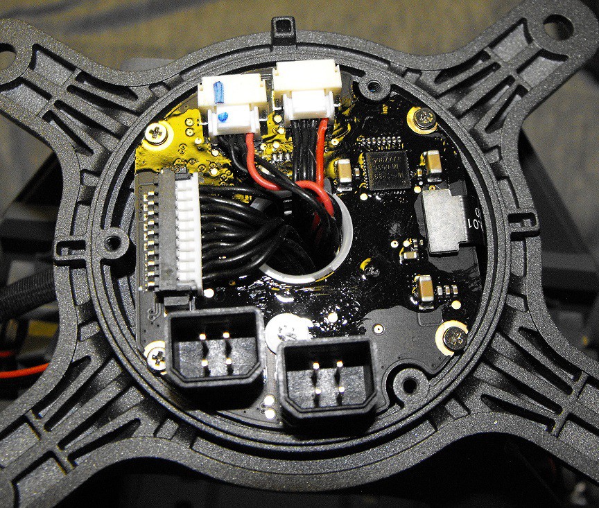
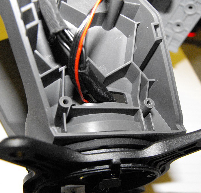
Above is the inside of the base enclosure. The connector to the brushless motor can be seen in the left side of the photo. This connector is held in place with a rubber pad on inside of the base's cap.
There's a another "cap" like covering one the top side of the turret base.
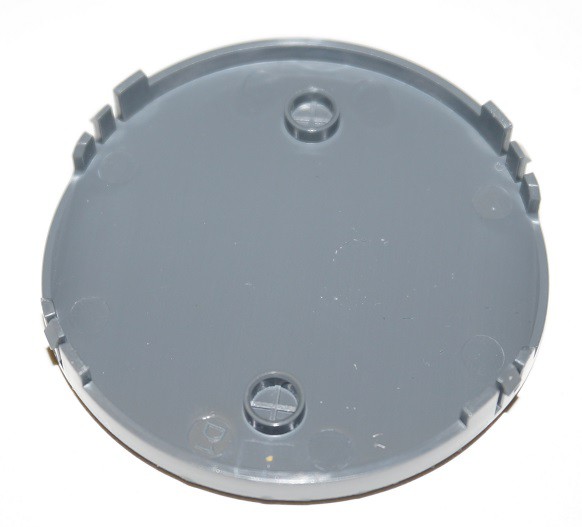
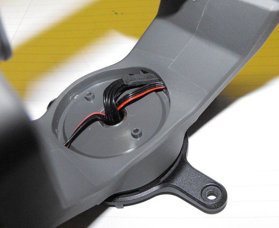
Wires to the turret hit detectors are routed through this space. The ten wires which connect to the tilt PCB are also routed here.
Discussions
Become a Hackaday.io Member
Create an account to leave a comment. Already have an account? Log In.
I thionk your guess about one of the chips being the controller for the brushless motors make sense: https://www.monolithicpower.com/en/mp6536.html
Are you sure? yes | no
Good catch. From the datasheet, we can deduct that the MPS1839 marking means the chip was manufactured in week 39 (1st week of October) of 2018.
It's also interesting to note that the turret yaw controller motor is controlled via a PWM signal vs CAN for the M3508I motors.
Are you sure? yes | no
While the ESC chip appears to use PWM as input, I'm pretty sure the input is from on microcontroller on the other side of the PCB.
There's an IMU up in the tilt section of the turret. I don't know if the IMU PCB talks directly with the turret base PCB (there are a couple possible wires it could use) or if the IMU data is first processed by the intelligent controller.
The M3508I motors on the S1 don't use normal CAN messages. It uses an 8-bit asynchronous protocol. This is very stange since some of DJI's other Robomaster motors use the CAN protocol. The orange motor bus is very different than the black CAN Bus. There's some more info in this thread post:
https://forum.dji.com/forum.php?mod=viewthread&tid=197642&extra=page%3D1%26filter%3Dtypeid%26typeid%3D703%26typeid%3D703
Are you sure? yes | no
Excellent! Thanks for finding that datasheet. I'll add it to the list in the "Details" section.
Are you sure? yes | no
Using a violet laser, I was able to read the markings on the chip I assume is a mircocontroller.
The microcontroller chip has the following markings:
Top Line: GD32F 33G
2nd Line: C8T6
3rd Line: BK52KQ
4th Line: JJ1831
Bottom Line: Some sort of logo and the text "ARM"
If anyone has any ideas about which chip this is, I hope they let me know.
Are you sure? yes | no
Maybe this? https://www.gigadevice.com/products/microcontrollers/gd32/
Are you sure? yes | no
The microcontroller could be made by GigaDevice but I wasn't able to find a direct match for any particular chip.
Thanks for all your help in identifying so many of these chips.
Are you sure? yes | no