 Duane Degn
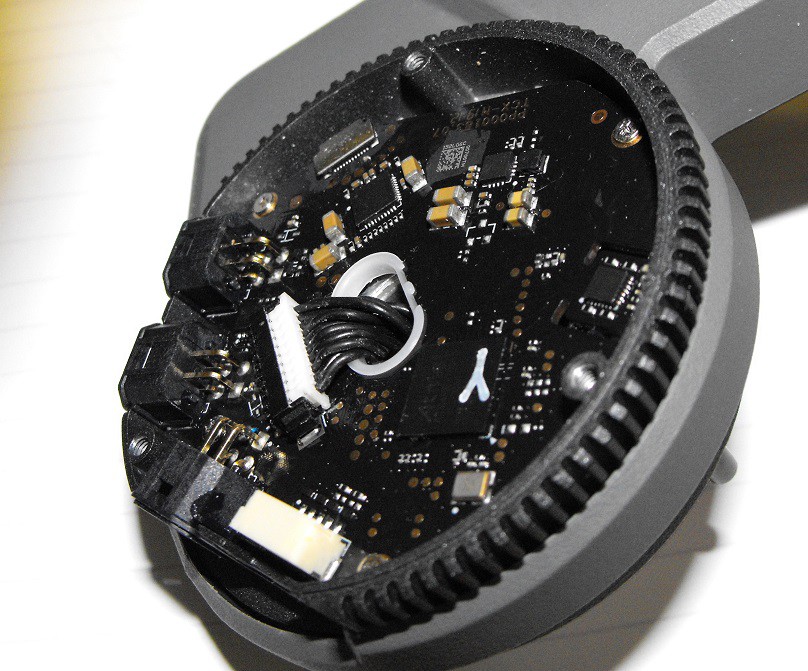
The brushless motor on the right side of the turret tilts the Intelligent Controller, gel bead gun and camera. The motor is controlled by circuits located between the tilt mechanism and the brushless motor.
It's a bit of a pain to reach this PCB. The tilt mechanism needs to be removed. There are three fasteners on the right side of the mechanism which need to be remove.
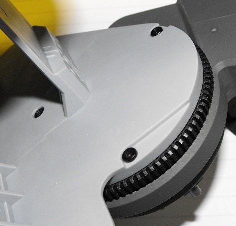
There's also a fastener on the left side which needs to be removed.
The above fastener can be removed with a T10 Torx bit. The hex driver which comes with the Robomaster S1 will work with this fastener in a pinch. I didn't realize it was a Torx socket until I saw this photograph.
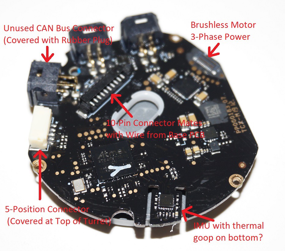
The tilt motor uses the same MP6536 motor control chip as the pan motor. Below is a closeup of the Atmel microcontroller chip.
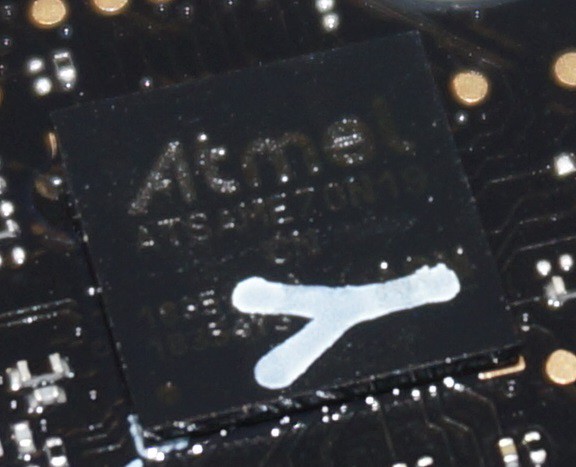
To me the text reads Atmel ATSAMEZON19. I haven't found the datasheet for this chip yet.
Edit: It's a ATSAME70N19. I can easily find the datasheet now.
The IMU chip is almost readable.
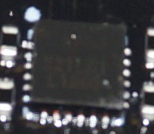
Based on this Chinese forum post, apparently DJI likes to use the "6500" IMU in other Robomaster products. I assume this would a be a MPU-6500 chip but I'm not positive.
There is some goop on the underside of the IMU on the PCB.
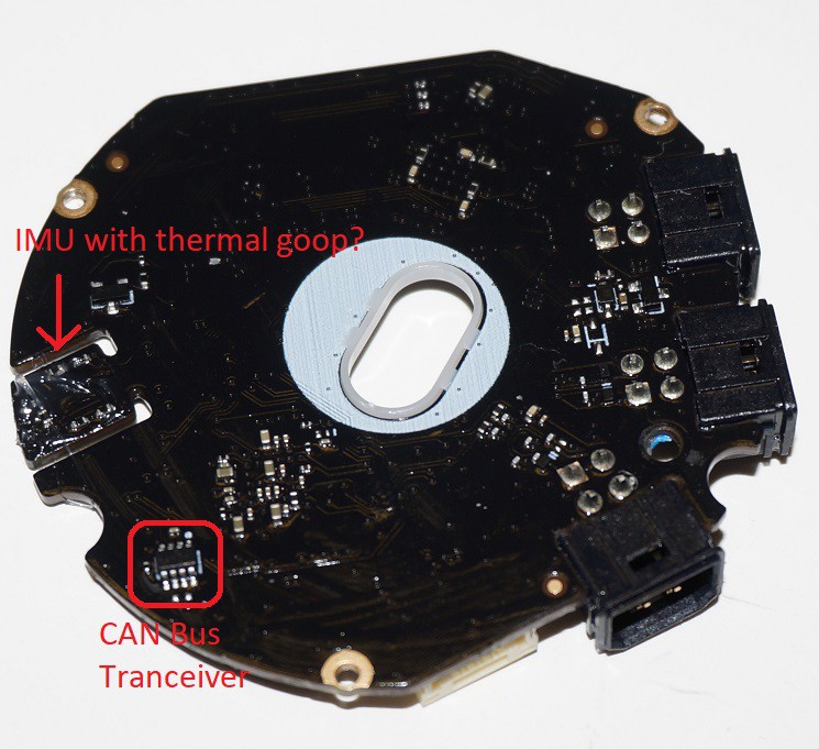
This goop is also on the metal support piece.
There's a small area walled off to isolate this sticky goop. I believe this thermal compound is intended to bridge the gap from the PCB to the metal support.
The brushless motor has 15 poles.
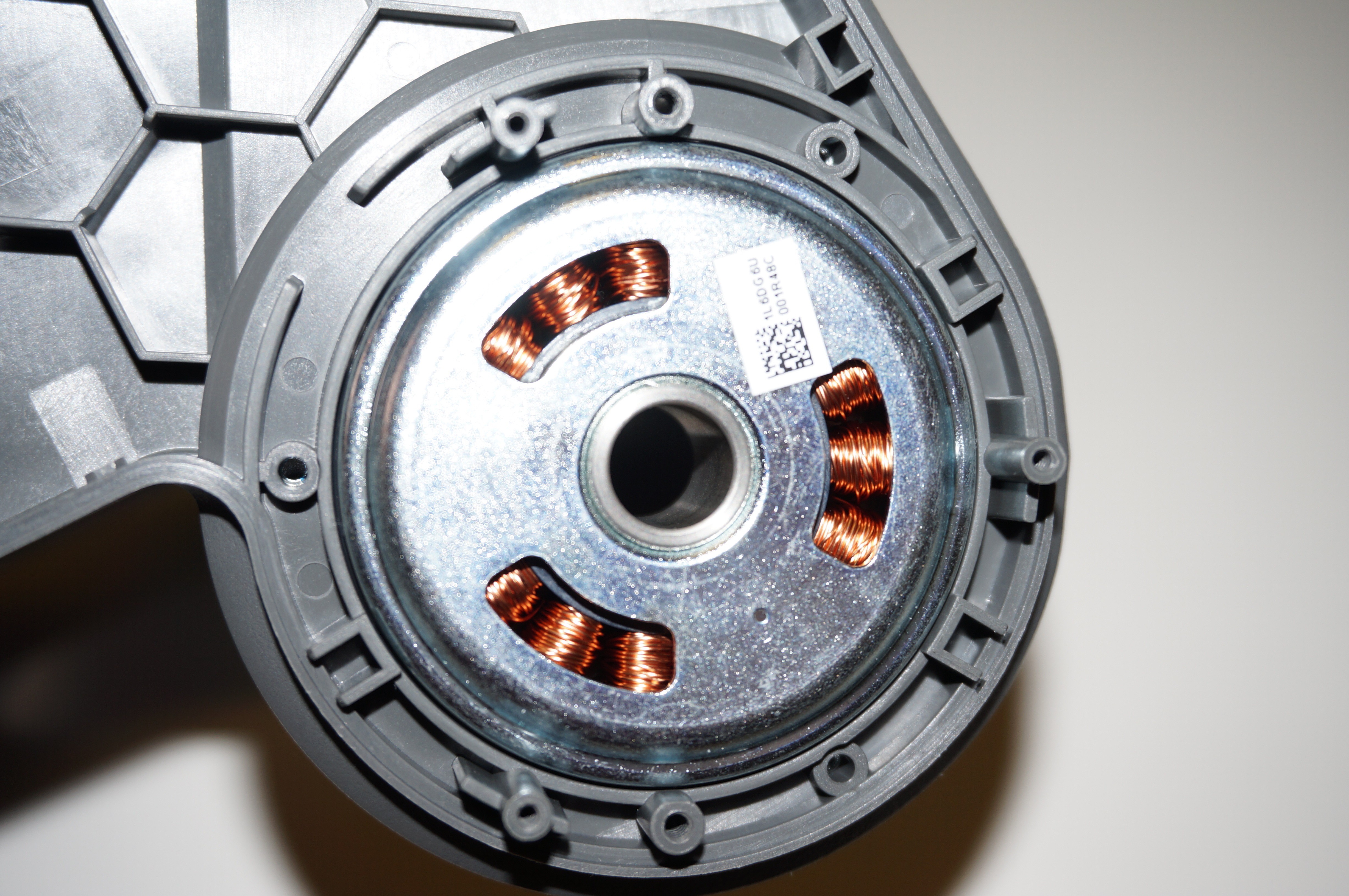
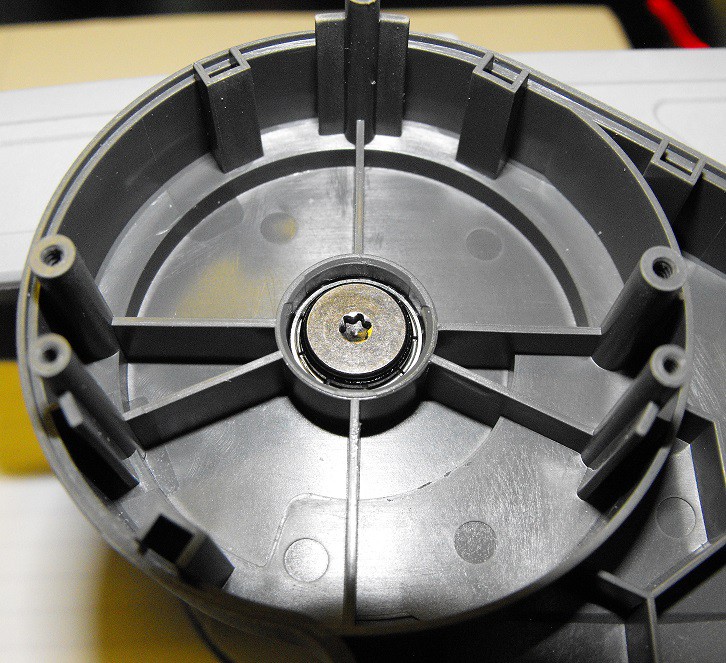
Three of the above screw holes serve an unknown purpose. Without disassembling the motor from the rest for the turret, I haven't been able to figure to what the three fasteners connect.
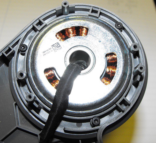
Here's another photo with the three fasteners in position.
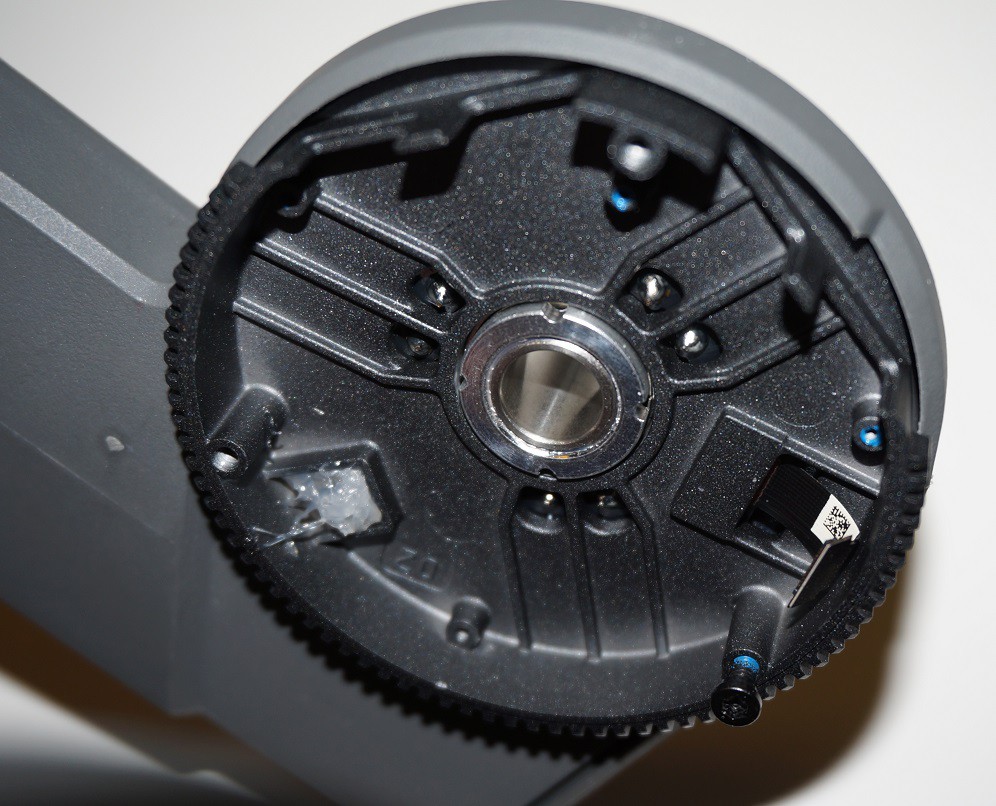
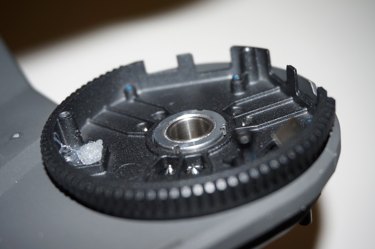
The metal PCB support piece rotates with the motor. The other side of the tilt mechanism rotates around the single fastener with a matching bearing and plastic spacer.
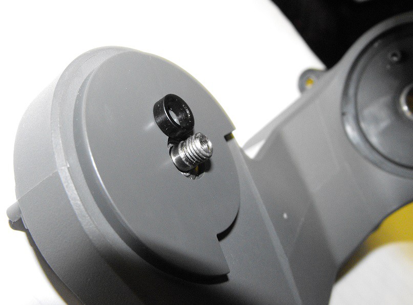
The fastener is supported by a bearing in the right side of the turret.
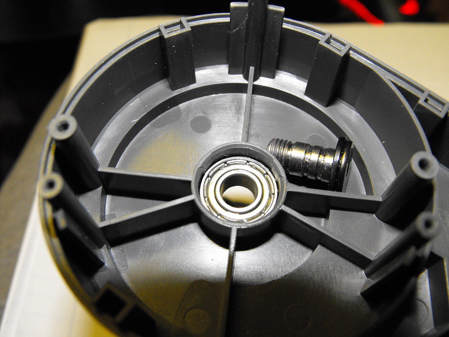
The fastener connects with the central tilt mechanism.
The geometry of the two mating sections limits the amount of tilt possible.
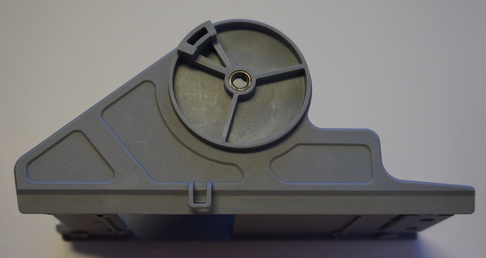
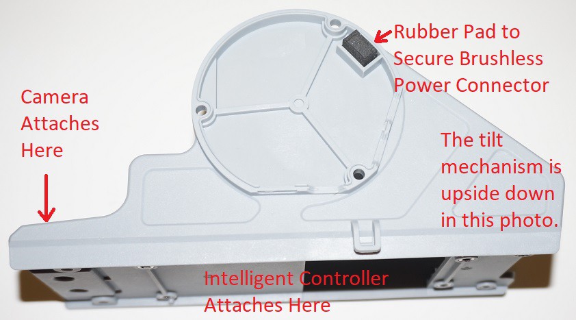
The right side of the mechanism mates with the metal PCB base. The right side includes a piece of rubber to secure the brushless motor's power connector.
One last note about the turret PCBs. There are multiple places where little stainless steel screws are used. Screws with different threads can look very similar.
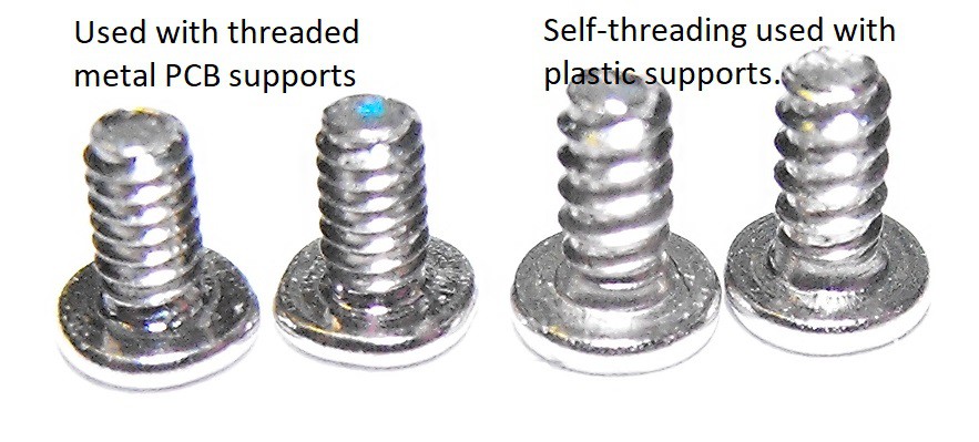
The self-threading screws are not used with the tilt portion of the turret. The self-threading screws are used to connect the turret hit detector PCBs the plastic supports. The self-threading screws are also used to secure the IR shield to the IR daughter boards connected to the turret hit detectors. See earlier log for turret hit detector tear down.
Discussions
Become a Hackaday.io Member
Create an account to leave a comment. Already have an account? Log In.