 danjovic
Working around joystick port differences
The most notorious difference is the negative rail pin, being the GND at pin 8 of the Sega Master System controller port but in MSX the GND is at pin 9.
A couple of diodes is used to route either GND pin to the negative rail (GND) of the arduino board.
HOST Auto Detection
The state of pin 9 at power up is used to detect which host the circuit is connected. Pin 9 is a input on SMS and therefore shall high (pulled up, indeed). On MSX this pin will always LOW as this is a GND pin.
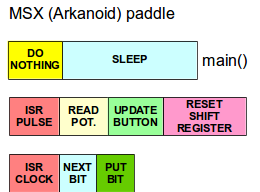
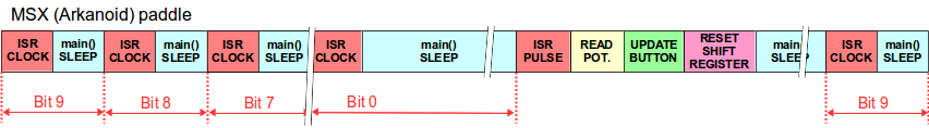
MSX paddle program flow
The MSX paddle follows the Taito Arkanoid model.
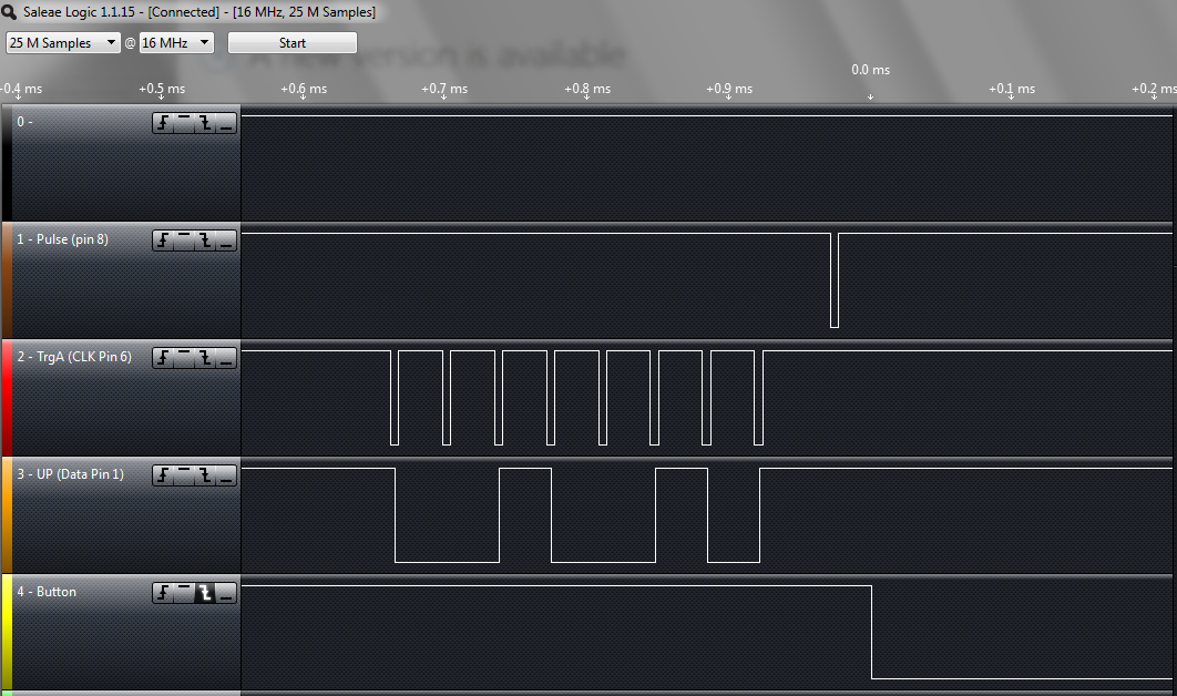
Each data bit is sampled then a brief low going clock pulse is generated by the MSX on pin 6 to shif out the next bit (data changes on risign edge). After the 9th bit is read another short going pulse is generated this time on pin 8. The rising edge of such pulse starts an ADC conversion. After the conversion is complete the most significant bit gets ready at pin 1 and the remaining bits are stored in a variable to be shifted later by pulses coming from pin 6. Button is sampled right after the conversion and pin 2 is updated accordingly.
Code is implemented using a couple of interrupts, one on pin 6 (clock shift) and another at pin 8 (start new sample). Main loop does nothing else than put CPU to sleep.
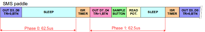
SMS paddle
SMS paddle sends one nibble at a time at a rate of 8kHz (62.5us per nibble). Each nibble is signaled by the level of pin 9 ("0" for lower nibble,"1" for higher nibble). The potentiometer is read right after the higher nibble is put on the outputs, then the button is read and pin 6 is updated accordingly.
Timing synchronization is done by use of a timer that wakes up the AVR.


 Marcin Saj
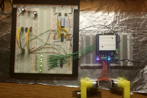
 Estudio Roble
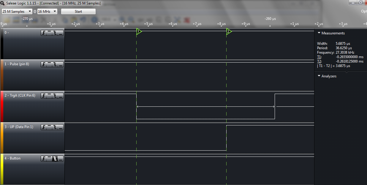
curiosity if you have a scan saved. I want to know if the sms paddle runs the clock 24 7. Does it ever sleep. But more importantly I was hoping to know if the console reads it full time ( guessing not). Would need to look at the game code for that. Also at what point does it read data. I gathered it was around 10 after rise/fall of trigger.