 davedarko
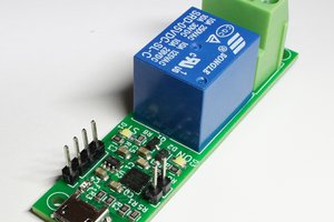
Relay module is called R421A08
- Working voltage: DC 12V ( going to an LM7805 without cooler)
- Working current: Standby 12 mA + 27mA per relay
- Open, close, jog, self-locking, interlock, delay six kinds of work modes
- MODBUS command control mode
- Maximum delay 255 seconds under MODBUS instruction
- MODBUS command In addition to the serial port super terminal input, but also can be used "Modbus Poll" input
- MODBUS command mode, up to 64 devices can be used in parallel
- Size: 90 * 62 * 19.5mm
- Weight: 115 grams
- Maximum load: 10A / 250VAC, 10A / 125VAC, 10A / 30VDC, 10A / 28VDC, 10A / 12VDC
Details download from here (copy and paste open)
/*

  based on code by youtube Adam Maszynotwór
  8-channel module RS485 DC DC 12V Modbus RTU 485
  Przykładowy program do płytki z 8 przekaźników sterowanych przez RS485 Modbus
  based on: Modbus RTU Client Kitchen Sink
  https://www.arduino.cc/en/ArduinoModbus/ArduinoModbus

  https://onedrive.live.com/?authkey=%21AHMWY%2DWpVi%5FfgPI&cid=41BCA72A6F31C9BD&id=41BCA72A6F31C9BD%21687&parId=41BCA72A6F31C9BD%21686&o=OneUp

  board control description :
  the sign 0x0 means that the entry is hex in brackets gives the values dec

  no. you select devices (slave address) thanks to DIP Switch (switches on the board)

  register no. - the relay is another register

  0x0001 (1)
  0x0002 (2)
  0x0003
  0x0004
  0x0005
  0x0006
  0x0007
  0x0008 (8)

  Commands
  0x0100 (256) ON
  0x0200 (512) OFF
  0x0300 (768) toggle Change state if ON changes to OFF lob if currently OFF it changes to ON
  0x0400 (1024) puts out all the other lights selected
  0x0500 (1280) extinguishes all and switches the selected one for 1 sec
  0x0601 - 0x06FF (1537-1791) is a time switch on from 1-255 sec

  zainstaluj biblioteki !
  <ArduinoRS485.h>
  <ArduinoModbus.h>
*/

#include <ArduinoRS485.h> // ArduinoModbus depends on the ArduinoRS485 library
#include <ArduinoModbus.h>

void setup() {
  Serial.begin(9600);
  while (!Serial);

  // Serial.println("Modbus RTU Client Kitchen Sink");

  // start the Modbus RTU client
  if (!ModbusRTUClient.begin(9600)) {
    Serial.println("Failed to start Modbus RTU Client!");
    while (1);
  }
}

#define SWITCH_ON 0x0100
#define SWITCH_OFF 0x0200
#define SWITCH_TOGGLE 0x0300
#define SWITCH_1SEC 0x0601

void loop() {

  // for (int id = 1; id < 3; id++)
  // {
    // this command corresponds to the modbus 6 command,
    // i.e. writing to a single register ModbusRTUClient.holdingRegisterWrite
    // - it is the address of the device 1,
//    - it is the register number 0x0001,
//    - it is the value to be assigned in the register 0x0100);
    // in other words, we send the command 01 06 0001 0100 (the checksum is calculated automatically)
    ModbusRTUClient.holdingRegisterWrite(2, 0x0001, SWITCH_1SEC); // SWITCH_1SEC
    delay(2000);
  // }
}


 cdh
cdh
 ElectroBoy
 Olek
Olek
Solenoid drivers often have a higher voltage/current pull in pulse, followed by a lower voltage/current hold in state. This minimizes heating in the coil and keeps enough force on the initial actuation to make sure the mechanism operates reliably. Some pinball flippers of old used this method. The only solenoid actuated door lock that I have seen the insides of, used this approach. Note that this is not the lock system where the electro-magnet actually keeps the door closed, those are different.