Close
0%
0%

PCB Lamp

A motion-activated lamp, entirely planned, designed and manufactured at the DesignLab

Public Chat
Similar projects worth following
A motion-activated lamp. Entirely planned, designed and manufactured at the DesignLab.

The idea behind this project is to create a product that can be made entirely at the DesignLab, using the equipment available at hand. It should be relatively easy to put together, not (that much) labor intensive, and interdisciplinary.

For this project I have the help of my amazing team members: Voja Antonic, Bruce Dominguez and Erika Earl.

PCBLamp BOM.xlsx

Electronics BOM

sheet - 12.20 kB - 09/04/2019 at 00:14

Download

  • 1 × Lamp body Black acrylic
  • 1 × Base Black acrylic
  • 1 × PCBA Connectors and Accessories / FFC, FPC Connectors
  • 1 × Battery holder
  • 1 × Infrared sensor wall

View all 6 components

  • Postmortem

    Giovanni11/04/2019 at 18:59 0 comments

    It seemed uncomplicated at the beginning!

    Now that the project is completed, here is a little postmortem.

    • The grid pattern on the lamp's body was a pain to remove until I realized I could use plastic scrapers/spatulas and remove it with great ease. 
    • Electronics required a few tweaks which I wish I could explain further but it is not my area of expertise
    • The only bridging issues we had with electronic components were for the motion sensor and microcontroller. Better solder paste, not too much solder paste on the stencil, correct temperature and uniform application help but still it is a little bit of an art. 
    • By popular demand, next version of the lamp will incorporate a magnifying lens. 

  • Fine tuning

    Giovanni10/18/2019 at 23:10 0 comments

    Well the boards and BOM have been ready for some time now so most of what is left is to plan manufacturing. Erika has been hard at work programming the last pieces and running test boards. A great way to test boards and be able to recover most of the components is by using double sided tape on it.  

    And just when everything seems to be working fine, the machine will act out and do one of these: 

    Yes... I don't think that would pass quality control!

  • Project management

    Giovanni09/27/2019 at 19:38 0 comments

    This was meant to be a simple product from the beginning, but from the beginning it was clear that no manufacturing project is ever "simple".

    I believe I mentioned this before. For the sake of organization you want the Manufacturing BOM separate from the Electronics BOM, but certainly, they live the same life. We may have planned everything smoothly for all the manufacturing, tool-making, etc, just to get a notification like this:

    We do not want a notification like this. 

    This is when services such as Findchips come in handy (Full disclosure, both DesignLab and Findchips are owned by Supplyframe Inc.). I am a Product Designer so I do not make the most of the service, but Erika does and that is really cool.


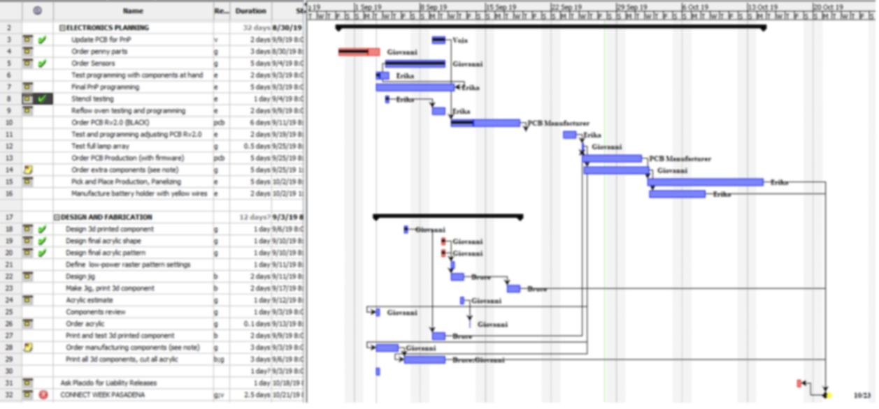
    One of the tools that I use a lot is a Project Management application called Project Libre (https://www.projectlibre.com). It is a simplified version of Microsoft Project without the price tag. The biggest drawback would be the fact that it is difficult to share the information with anyone who does not have the software (along with a few glitches here and there), which could be an advantage if you look at it from a different perspective :)

    I have tried creating complicated spreadsheets in Google or Excel together with Gantt charts, but I quickly end up missing the degree of control that you can have with a project management tool. Being able to select who works what days, how many hours, what tasks begin before, after, concurrently in relation to other ones, etc., are just a few things that you could have with a spreadsheet but would take a loong time.  If you want to estimate with some decent accuracy how long a project will take, I would say this is the way to go.

  • Concealing the sensor

    Giovanni09/17/2019 at 18:03 0 comments

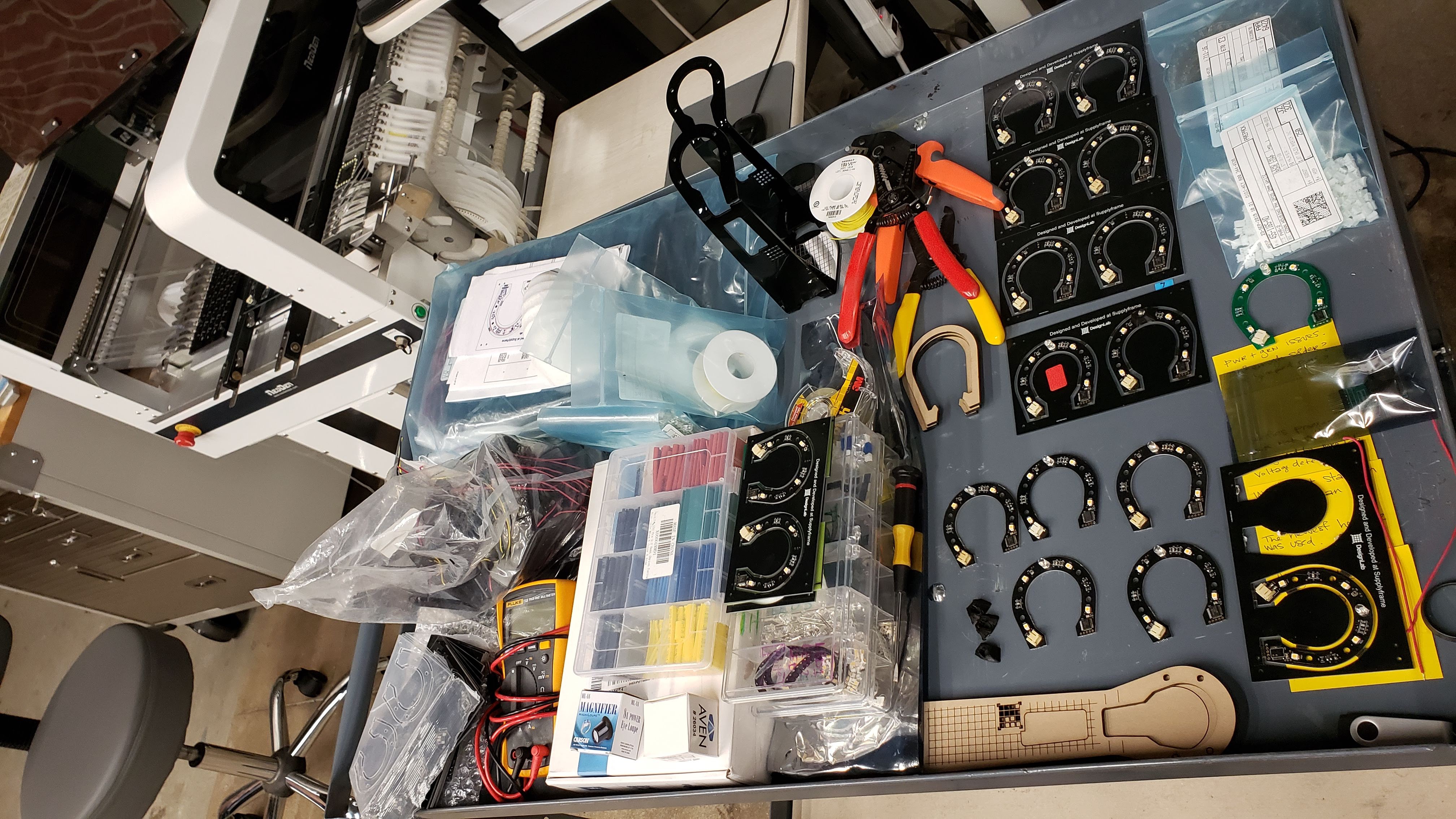
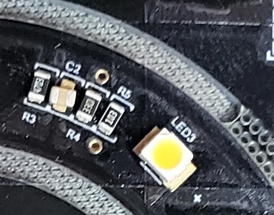
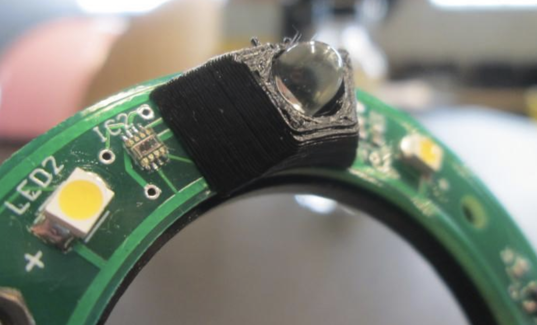
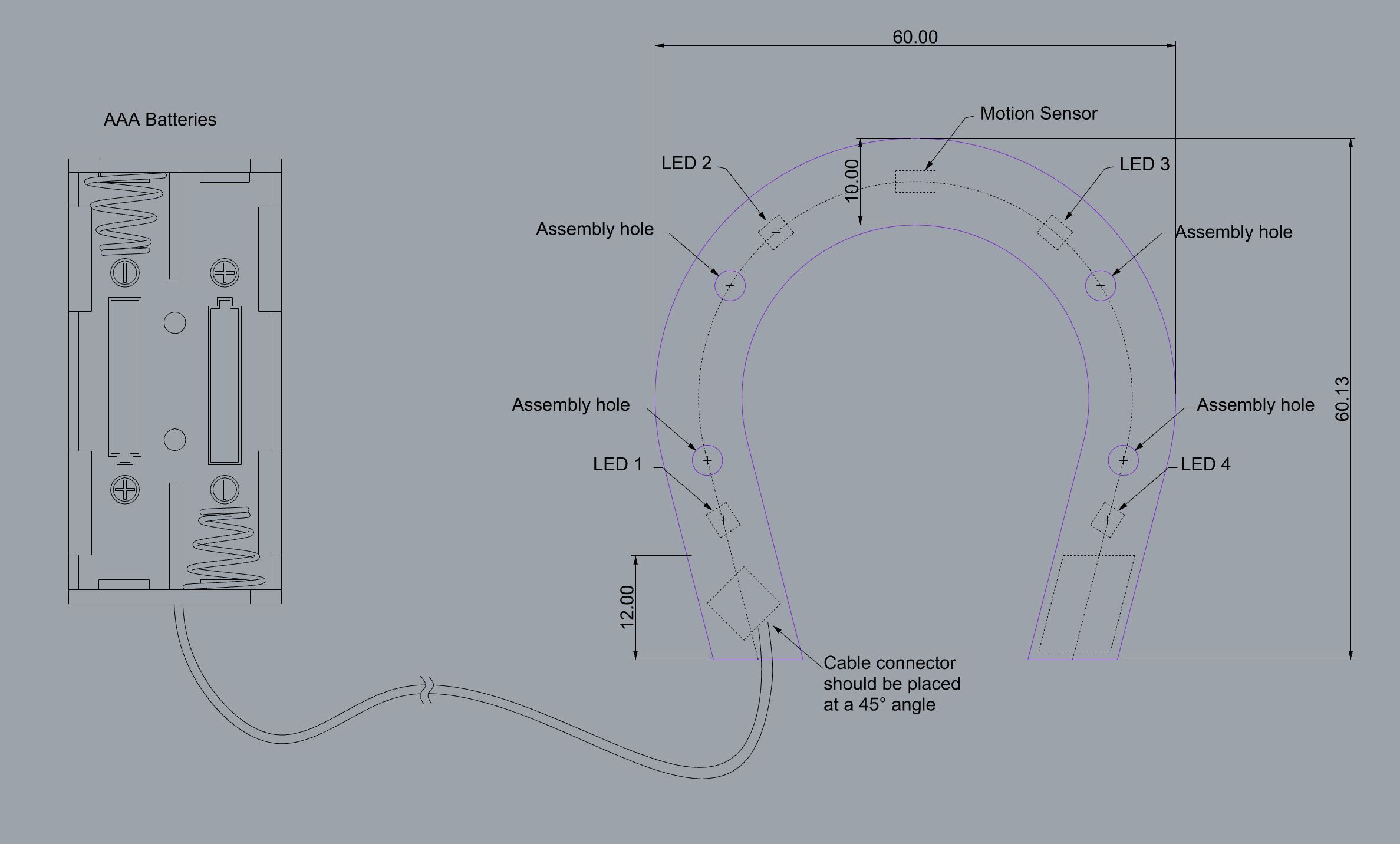
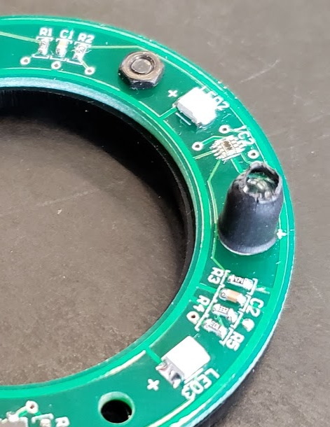
    We are using a 2-component motion sensor. It is actually just one sensor but it needs an LED next to it. Voja managed to put a shrink-wrap sleeve on it for prototyping but we have to plan something for production. Production that is, a few hundred pieces. It does not make sense to make a plastic injection mold for this, so we will go full on 3D printing.

    Since production PCB is going to be black too, the black printed component will blend nicely. Well, at least in paper. Here is a preliminary rendering and you can see how I deliberately let a section of the LED stick out  of the black enclosure. 


    After we printed it and tested it (thanks Bruce!), it turns out it is too short. For the sensor to work properly, the sleeve has to block the LED from it almost entirely. At least so that the UV light path does not cross right away. Otherwise, it will keep triggering the light unexpectedly

    Back to the drawing board!

  • PCBA planning for manufacturing (1)

    Giovanni09/14/2019 at 01:04 0 comments

    The first PCB panels we received had a minor but fatal flaw: no extra spacing to the sides, meaning that rails ended up blocking some of the traces. Erika improvised adapted and overcame the challenge by adding extra material to the sides in order to get us those badly needed 5 mm. Of course, this is a temporary fix and I just ordered new, improved boards today. 
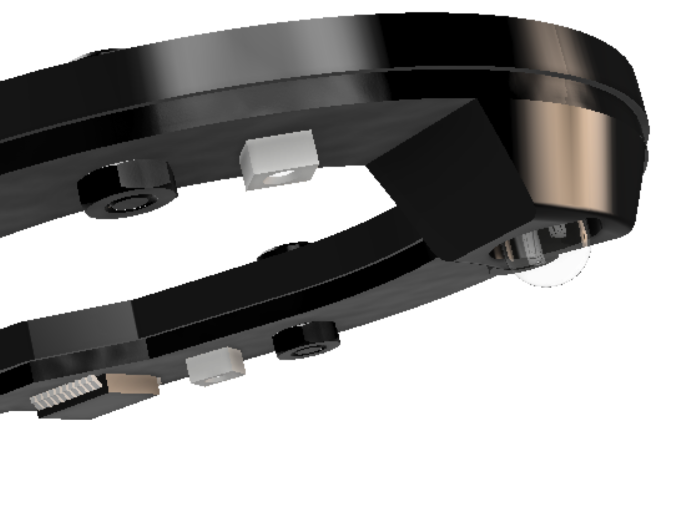
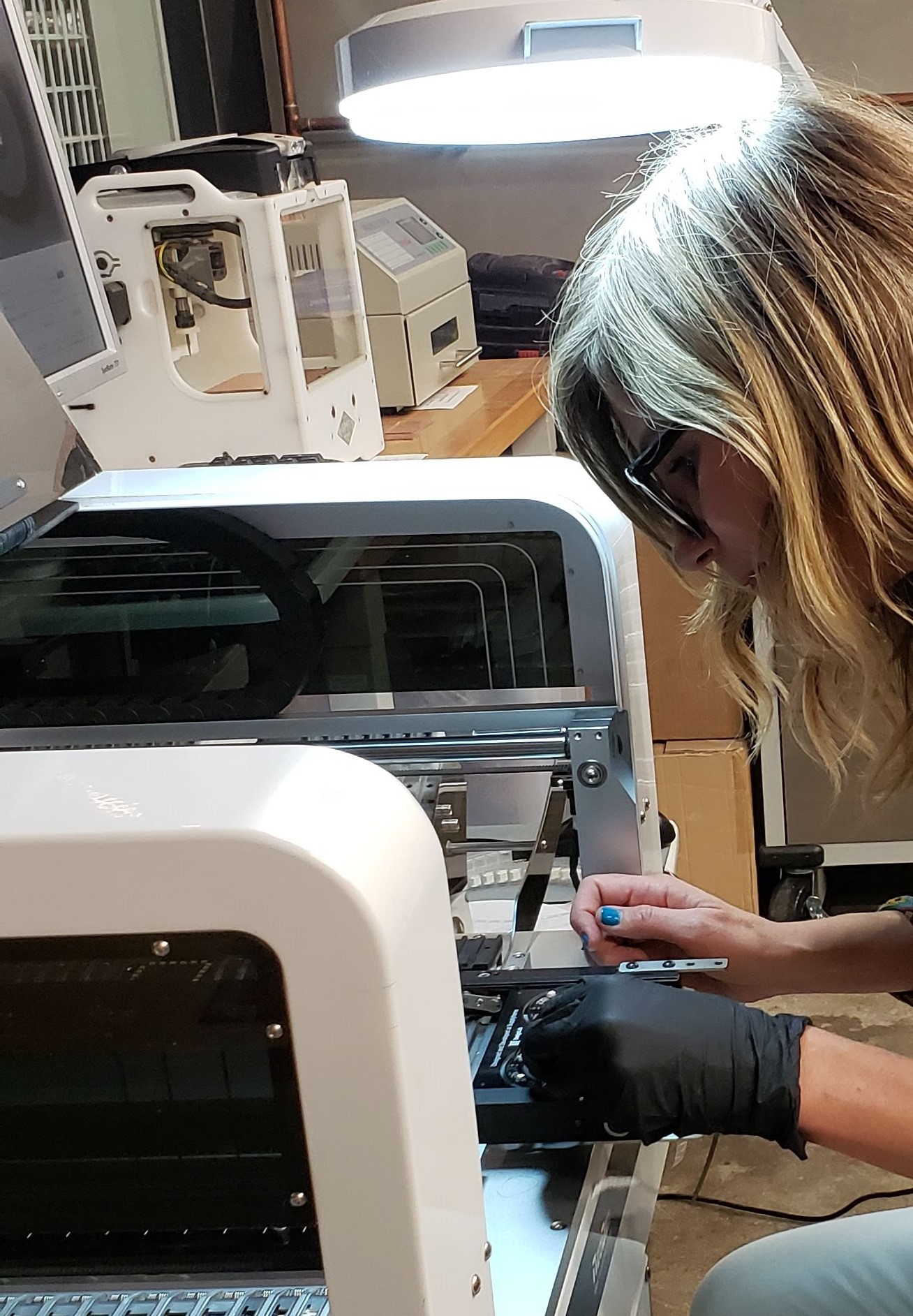
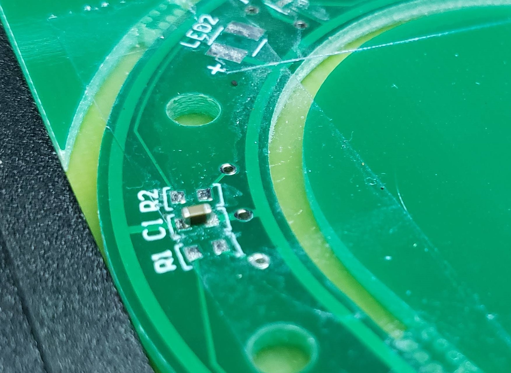
The precision on these machines is very good. The cycle to pick a component and place it on the board has quite a few steps that I am unable to describe, but Erika would in a heartbeat.  Essentially, the machine takes photos of the nozzle (?), board fiducials, grabs component, goes for another selfie and then flies over to the exact location where such component should be placed.

    This photo was taken by the machine after it placed that resistor on C1. See how well centered the component is on the board?  Now check out the next photo for a better idea of the scale.


    Pretty crazy, uh?

    Want to see the Pick and Place in action?  Grab your popcorn for an awesome 17-second video with the sequence I eloquently described above.


  • Designing the PCB

    Giovanni09/05/2019 at 00:04 0 comments

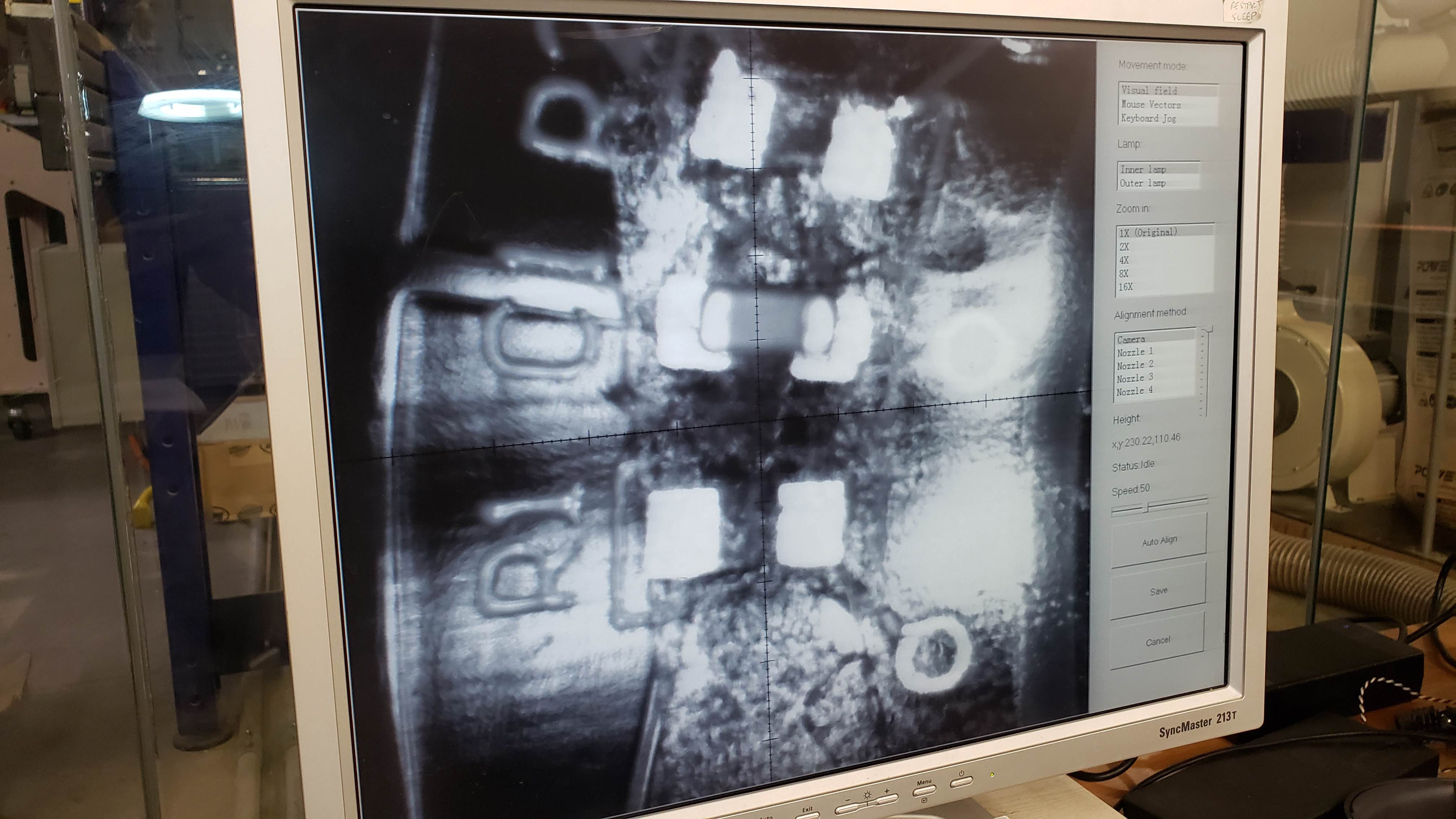
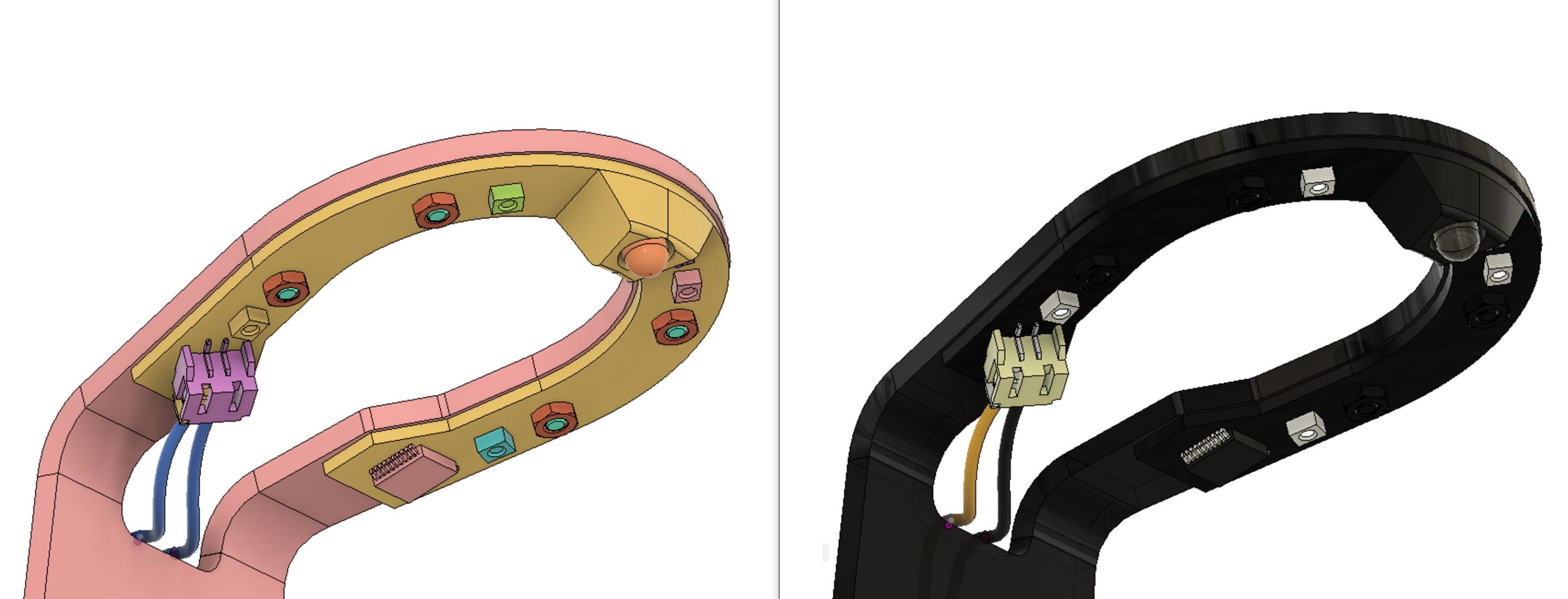
    This is a very interesting part of the process because here is where electronic engineers and product designers finally butt heads.

    Based on the design of the lamp, I shared with Voja a sketch with the ideal location of certain components on the PCB. I am not an electronic engineer, so there are many components I do not know we need and/or their location, therefore I try to keep my communication simple, detailing:

    1.  Basic shape or outline and assembly holes
    2. Location of input/output components (LED's, connectors, power source, etc)
    3. Other restrictions or requirements (light pipes, etc)
    4. Everything else I assume is going to be populated with a bunch of resistors, capacitors, micro controllers, etc.

    The electronic engineer (or yourself) might come back to you with further requirements, requests for more space, different orientations, etc. This is where the fun begins. Fortunately, this is a rather simple project so Voja managed to skillfully fit everything on a single board. Once that was confirmed, time to go back to the 3D model to update component location.


  • Product design and development

    Giovanni09/04/2019 at 00:11 0 comments


    Manufacturing processes were narrowed down to:

    • Acrylic cutting and engraving
    • 3D printing
    • Gluing and screws fastening

    The only process I did not entirely like for this project was 3D printing. Mostly because this is supposed to be part of a quick workshop and if you have done 3D printing you know how much of a mood killer it can be to wait 3 hours for a tiny-yet awkwardly oriented part on your printer. But the motion detector system needs a component that blocks the LED from the sensor up to a certain distance so with no other practical alternative, let us plan for printing in three dimensions.


    There is a rough first sketch of the lamp. The base did not look stable enough, and the shape was odd. 
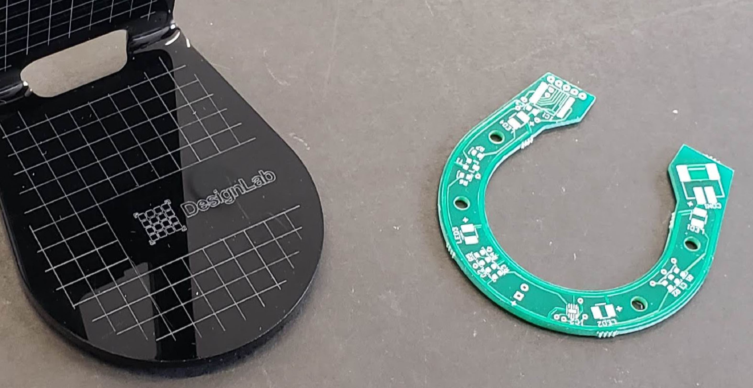
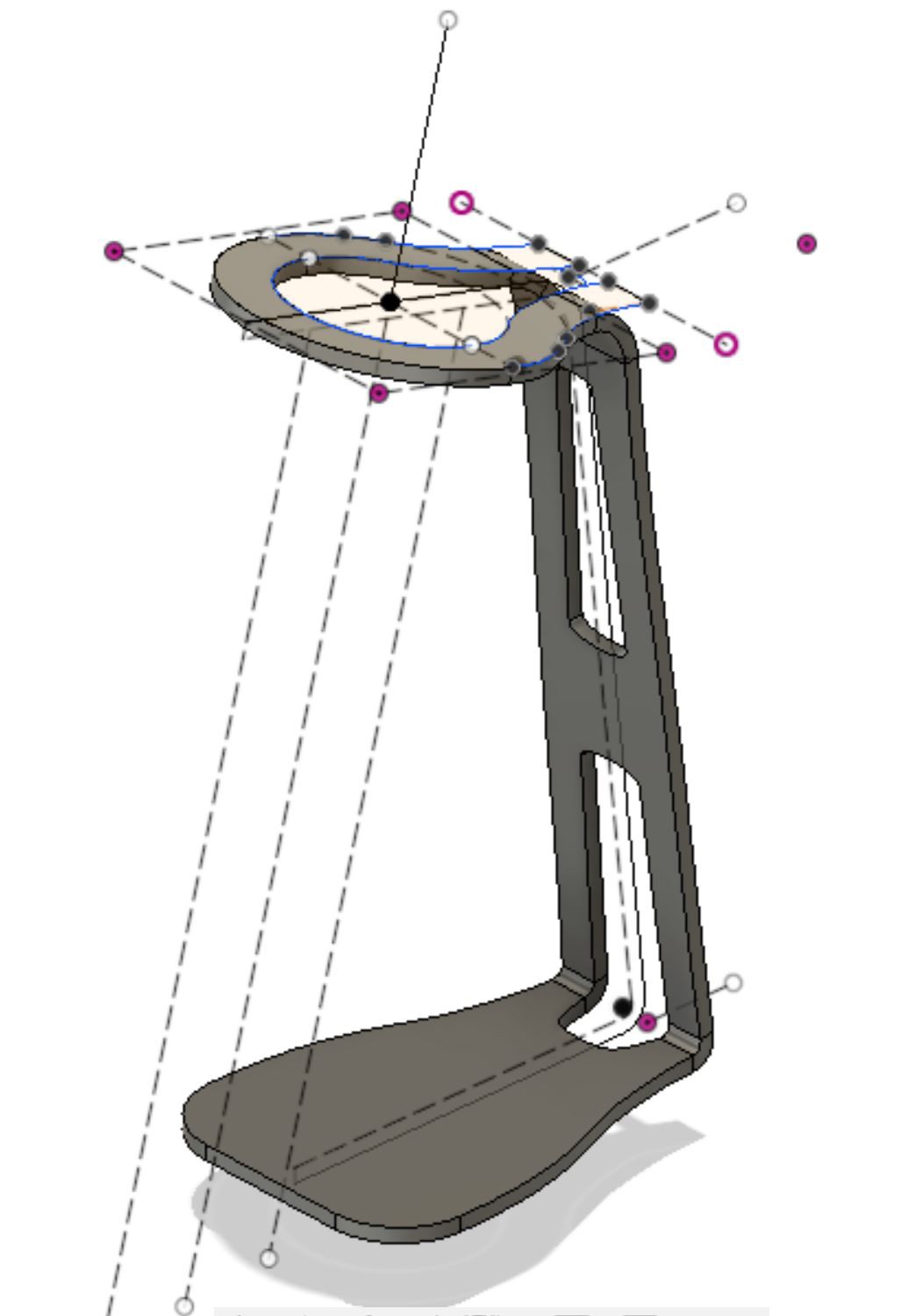
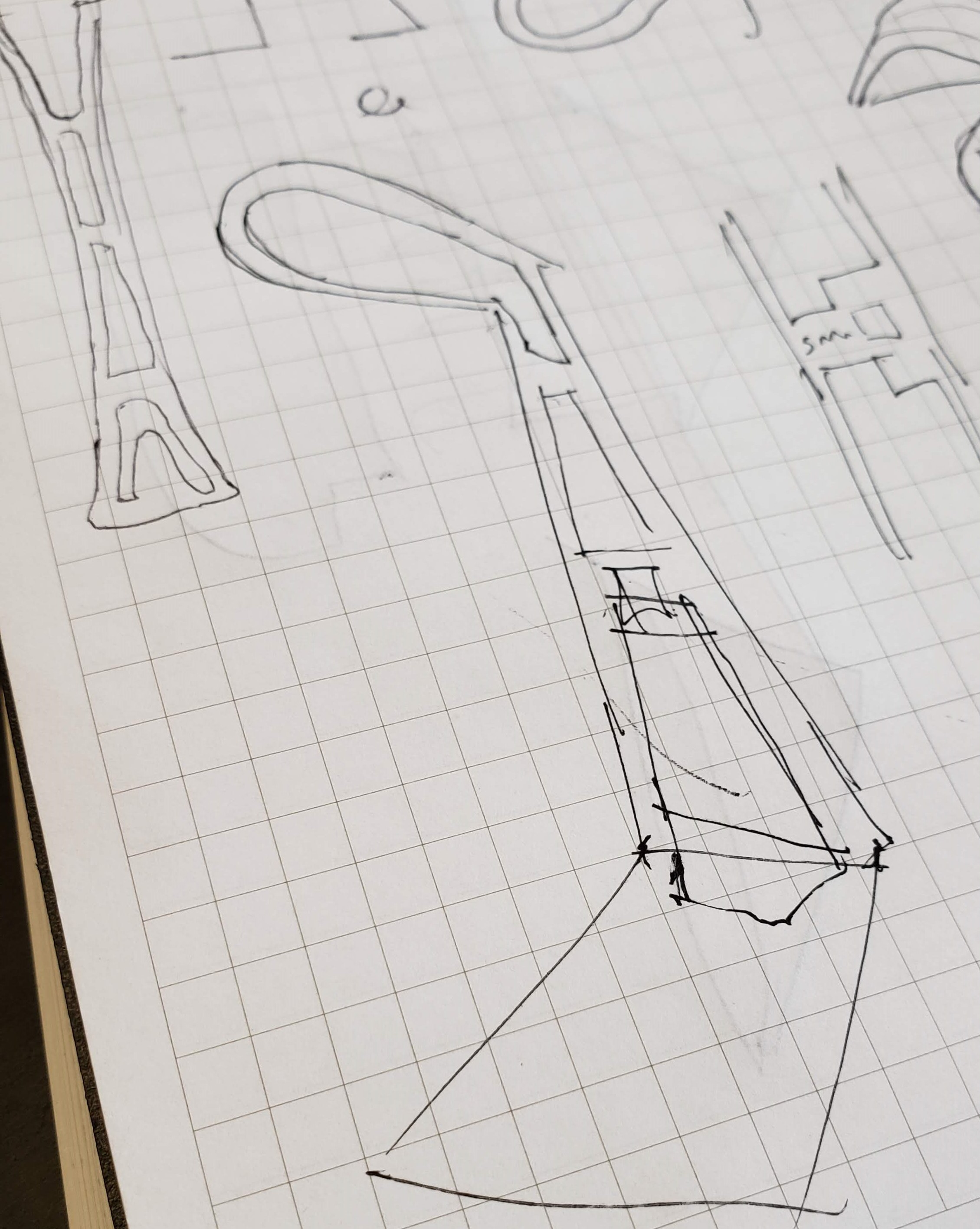
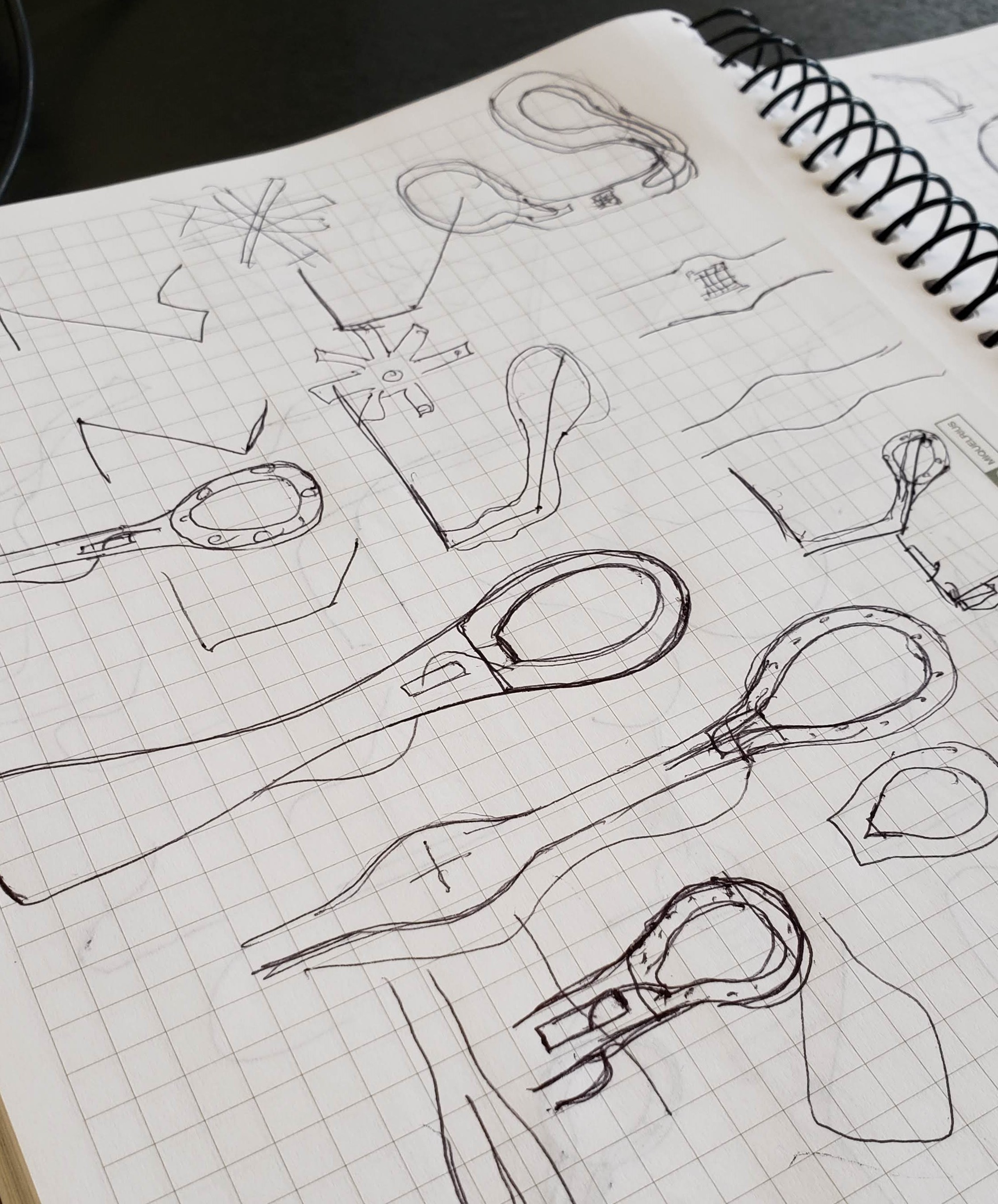
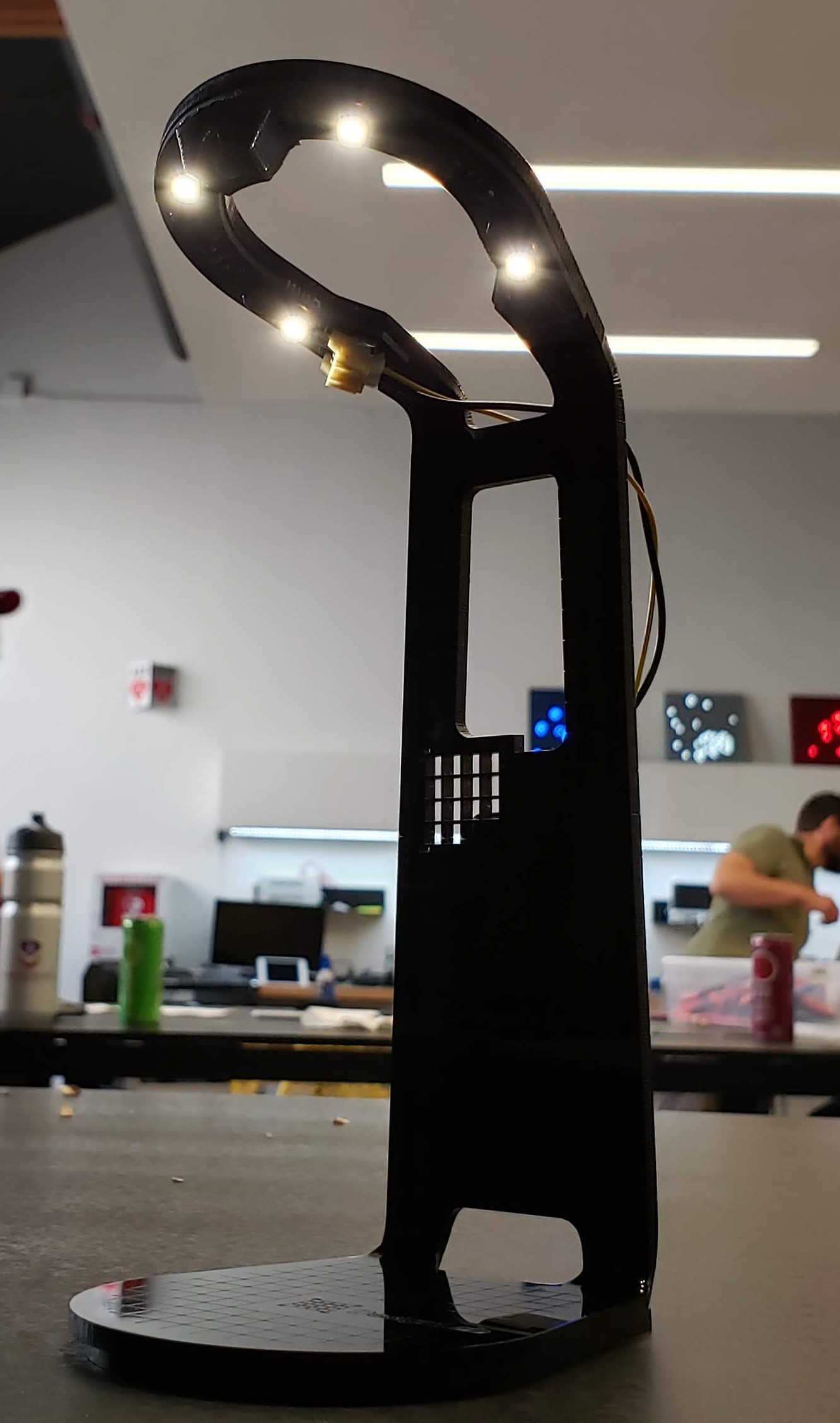
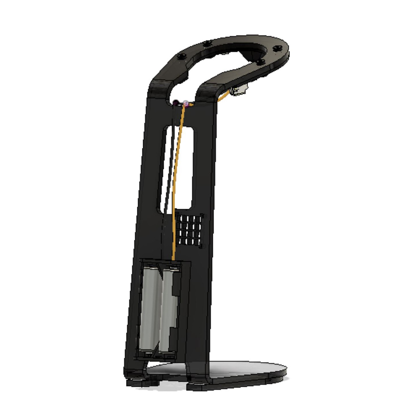
Still talking about the base, we went for a sturdier feel to it, a more geometric, kind of predictable-yet reassuring shape, and a little elevation which gives it a nice shadow and depth, plus increases stability. Batteries ended up fixed to the back.


  • Material selection, shape study

    Giovanni08/29/2019 at 18:03 0 comments

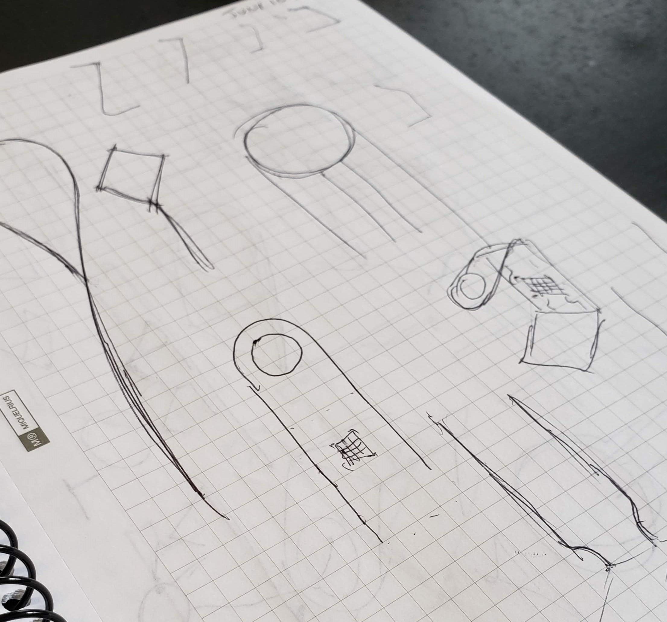
    We could say the process was started with the question: What simple, reasonably consistent and repeatable and processes is available at the Lab?  Laser cutting of course. There are CNC mills and 3d printers but with laser cutting, once you have a predetermined shape, it basically becomes a "push a button" task. The next step, acrylic bending is not too complicated and I am planning to make a bending jig out of MDF soon.

    Once I had material and process defined, it was time to go back to the sketches and try to come up with a simple, yet elegant shape. Disclaimer my sketches are far from elegant. Trying to hide the wires was hard and cumbersome, so I thought of "celebrating" them. More on that later. I bounced back and forth whether I should hide the batteries under the base, or behind the body.

    I decided to go for the back for the sake of an easier production.

    Talking about the light pattern on top, a flat base or a strip are too conventional, and I would like to have more people work with this shape and make it a different design. So I went for a "horseshoe" design for the light and PCB pattern.

    A perfect circle would be too strong in terms of visual communication and it could lead to the usual, clean, rational, minimalist design. 

  • The conception

    Giovanni08/28/2019 at 18:23 0 comments

    Image result for neoden pick and place

    One of the purposes for this project is to get the Neoden Pick and Place machine up and running. We created a simple product that could be easily programmable, and with as many Neoden compatible components.

    In that regard, we avoided through-hole as much as possible, and almost everything is SMD, including connectors.

View all 9 project logs

  • 1
    Acrylic cutting and bending

    (Work in progress)

  • 2
    Pick and Place assembly
  • 3
    Lamp assembly

View all 3 instructions

Enjoy this project?

Share

Discussions

Does this project spark your interest?

Become a member to follow this project and never miss any updates