 Matt
MattHave been continuing to lay out the board design in Inventor this week. I'm trying to design as much of this as possible in CAD now both to prevent screw-ups that would push my budget (trying to keep this entire project under $200) and to hopefully make this very repeatable for others who would like to try this as well. Additionally, since I'm trying hard to avoid machine tools, all the required 3D printed parts are being designed in place.
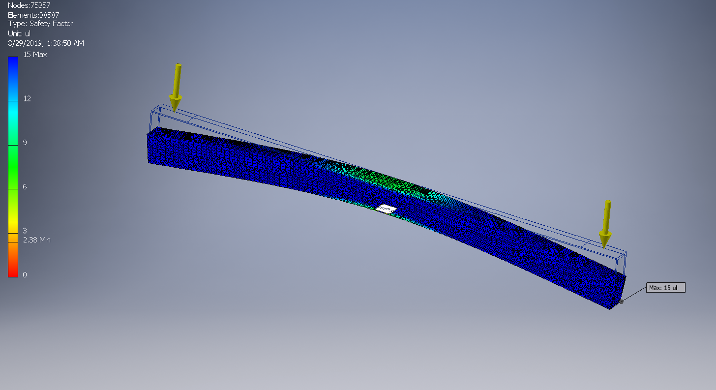
I Finally decided on 1.5"x1"x1/8" rectangular 6061 tubing for the frame rails, with 1"x1" (1010 80/20 extruded aluminum) cross bars. Ran a quick FEA stress analysis on one rail, with 100 lbf at each end of the rail. With a safety factor over 2.0 at 200 lbs (on one rail!) I think this Onewheel will be a-okay under my 150 lb body, even after I put a few holes in the frame.
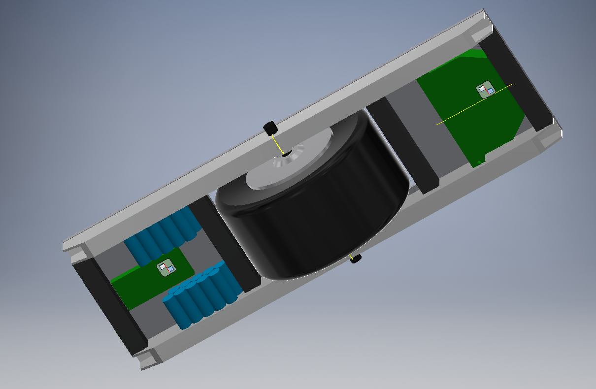
Top deck will probably be some plastic with skateboard grip tape. Electronics fit snugly, but they fit. There is some room for components to stack on top of each other if needed, but I want to give the motor controller as much room to breathe as I can. If I want to increase battery capacity later on, I might have to get creative with cell placement. For now, this has the same number of cells as the hoverboard battery pack, but in a different configuration. Should still have room to squeeze in lights, buttons, and maybe an arduino for speedometer, odometer, and power consumption monitoring later.
My new tire finally came in the mail, so I have measured and verified that it should work. This model is a Duro Excelerator. Seems like it should work very well, and has a nice sharp-ish edge for balance. Not bad for less than $40 shipped.
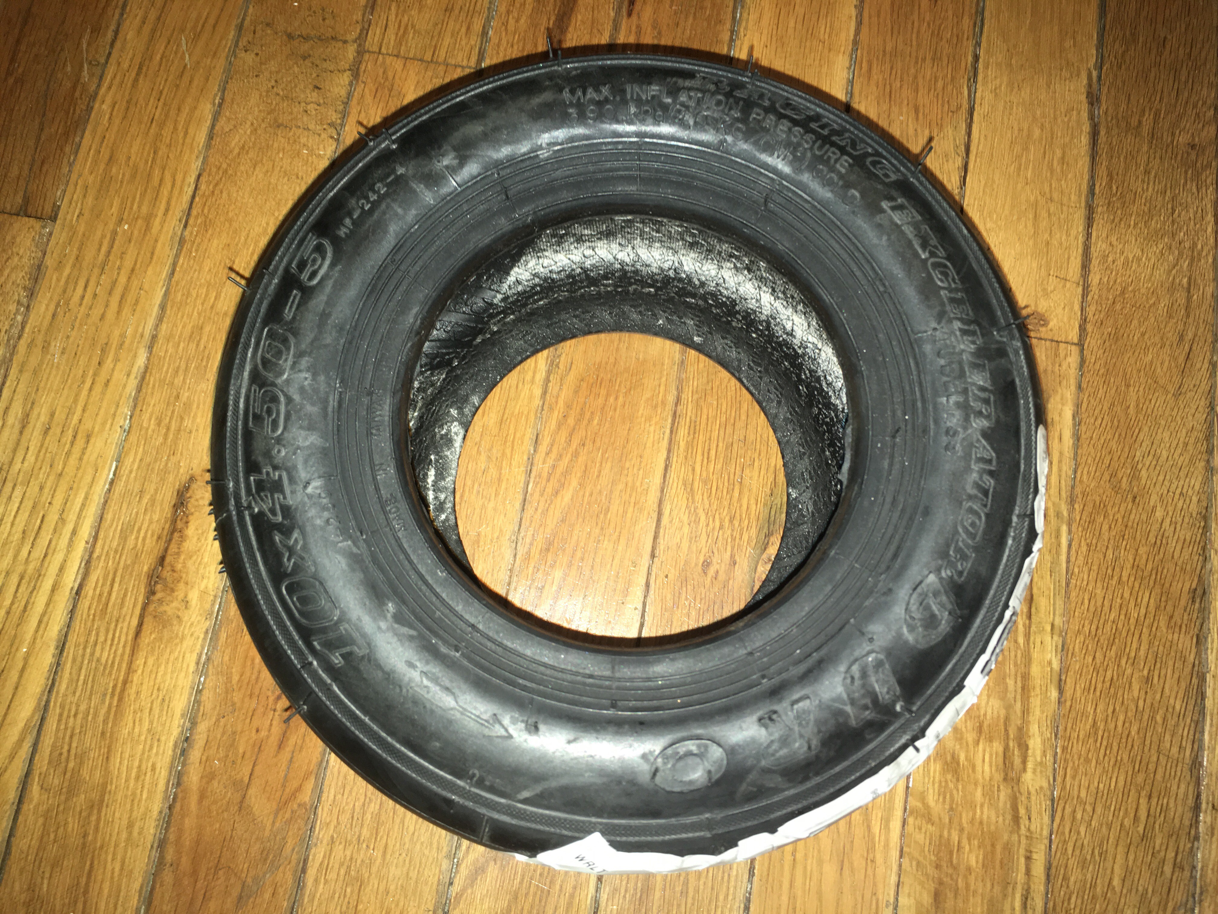
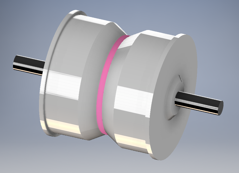
Like I expected, the tire is exactly 4.5" wide at the bead, which means I could go ahead and design the spacer which will be 3D printed to go between the two hub motors, shown here with their outer rings removed. Five holes will need to be drilled to accommodate the M4 bolts which run through the motor casings and the spacer holding the assembly together.
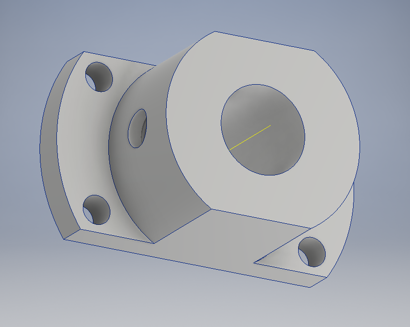
The motor assembly will be held to the frame using two modified versions of these hubs, although I may trial a 3D printed version as I'm really not looking forward to removing all this material so that the hub will fit inside the frame rail.
Despite the board not even having a physical form yet, I'm already thinking of ways to improve the rideability and performance. Although the motors are supposedly 350 W each, I'm suspicious that the electronics package and no-name 18650 cells don't deliver that kind of power. I have been wrong before though, and I'll surely be taking some measurements when all is finished. At the very least I expect I'll be adding a beefy capacitor across the battery terminals to help out with big load spikes, just in case.
To do: Some more CAD layout, design some endcaps/nosedive wheels, source some materials/tools, get some parts printed, then start working on configuring electronics and motors to work happily in their new home.
Discussions
Become a Hackaday.io Member
Create an account to leave a comment. Already have an account? Log In.