 Mike
MikeSUMMARY
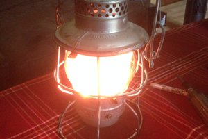
This project was a quick, fun modification of an old Halloween toy. I wanted something slightly different than what was originally on this, and an opportunity to experiment with different controllers using a PIR senor for a simple application.
HISTORY
A few years ago I had put together a similar project , but did not use a uC.
I had an ultrasonic sensor with output triggers for relays to the sound box and flash circuit.
GOAL
My goal was to merge these 3 systems quickly, using a uC. These 3 systems each have their own battery power, and are off-the shelf components. The sound box is from Electronics Goldmine; a small white box that scream "Happy Halloween!". The hack here was to pull the switch leads to to connect to a relay. The flash circuit is also from Electronics Goldmine, and is an old camera Xenon flash tube circuit. The hack here was also to have this activated off of a relay and to wire the circuit to continually recharge from it's 1.5V battery. I also added a switch on this project for power, in case the flash gets annoying! Oh, and just for fun I added a couple of pulsing LED's for eyes.....red, of course! And finally, the micro controller selection.
uC Comparisons
Using an mbed LPC1768 , I found the code very easy to write and get the project going, but quickly realized this beast running at 100Mhz and consuming ~150mA was way more than I wanted.
I then tried an old Arduino Nano I had, and found it pulling ~25-40mA , again fairly easy to have a HW interrupt for the PIR and overall code quickly completed, but a bit more power than I wanted running.
Then I dug out an old Parallax Basic Stamp I. My first run showed it pulling ~5mA with LEDs pulsing, with max current at 17mA. Not bad. But I wanted more battery life! Using Sleep and Nap modes, I am putting the toy to sleep most of the time, drawing 25uA.
SUCCESS!!
So, with about 1 week until Halloween and with 1 full day of gutting the old toy , drilling, hot-gluing, LED mounting, and minor firmware changes...here it is! All that is really left is to add a switch for the 9V connected to the BS1.
 Chris
Chris
 Gareth
 scubabear
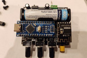
 samm928