 Dominik Meffert
Today I tested out to print something with the new design, but it did not really work as expected.
The good things are:
- The pumps can pump the ink up to the printhead and can eject ink out of the nozzles.
- If the pumps have enough power (when using two piezo discs) there is no problem with making bubbles.
- It's reliable. As long as there is no air in the lines it works without problems even after days of being not in use.
The only bad, but unfortunately essential thing is:
- It works good for streams of ink but not good for drops unlike the last design which, however did not work reliable.
So I have to find a way to get it more suitable for ejecting drops, somehow...
My first idea would be using DC again instead of AC.
I think the relatively slow rise of the voltage in the 50Hz mains sine wave could be the problem. With a DC square wave the voltage rise and therefore the piezo movement and ink pressure change would happen almost instantaneously what should be better for creating droplets.
The problem with using DC would be, that the piezo needs AC to move in both directions to perform not only a change in ink pressure, but a pumping action.
So the best should be a high voltage AC square wave.
At the moment I only have the parts to switch high voltage (up to 500V) DC.
I will try that out later, but it will likely not work and so I have to find or build something that can create a high voltage AC square wave....
I just figured out that the DC SSRs are really bad for switching the piezo disc compared to the IRFP460, so I will rather use these.
I built another printhead that has a drain directly underneath the nozzles to suck up the excess ink drops. It is mounted at an angle, so that ink drops do not form at the tip of the nozzle - what would block the nozzle - but instead form on the side of the nozzle until they drip into the drain.
For this printhead I used 0.1mm nozzles. With two piezos in the pump the amount of ink per drop is a bit high what I think leads to the drops that are forming on the nozzle, but using only one piezo in turn is too less ink what leads to no droplets at all.
I think the new printhead in combination with a PCB with four IRFP460 and a rectifier should make the design ready for first printing tests.
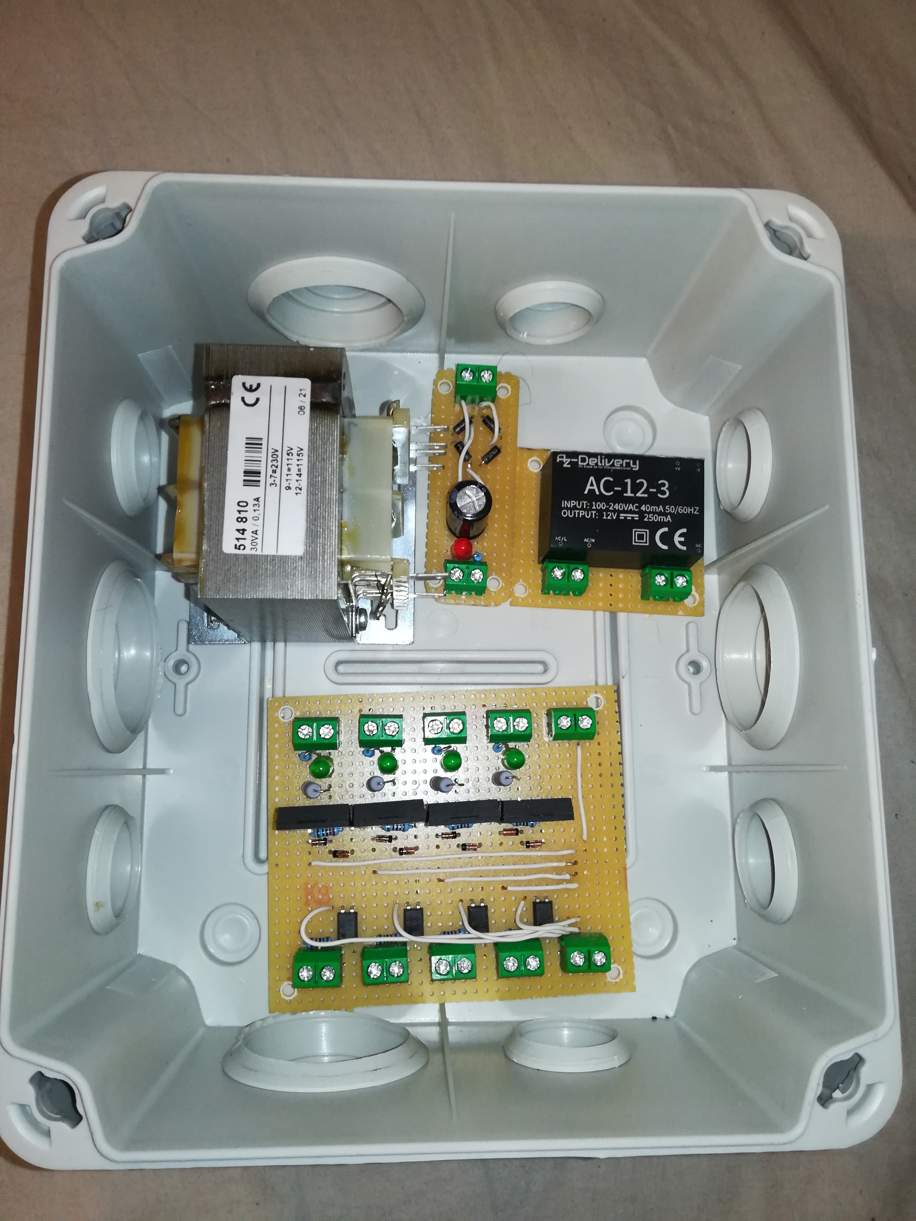
New electronics for the piezos.
A transformer, rectifier, 12VDC power supply for the optocouplers and a board with four IRFP460 and 47k 1W resistors for switching and discharging the piezos.
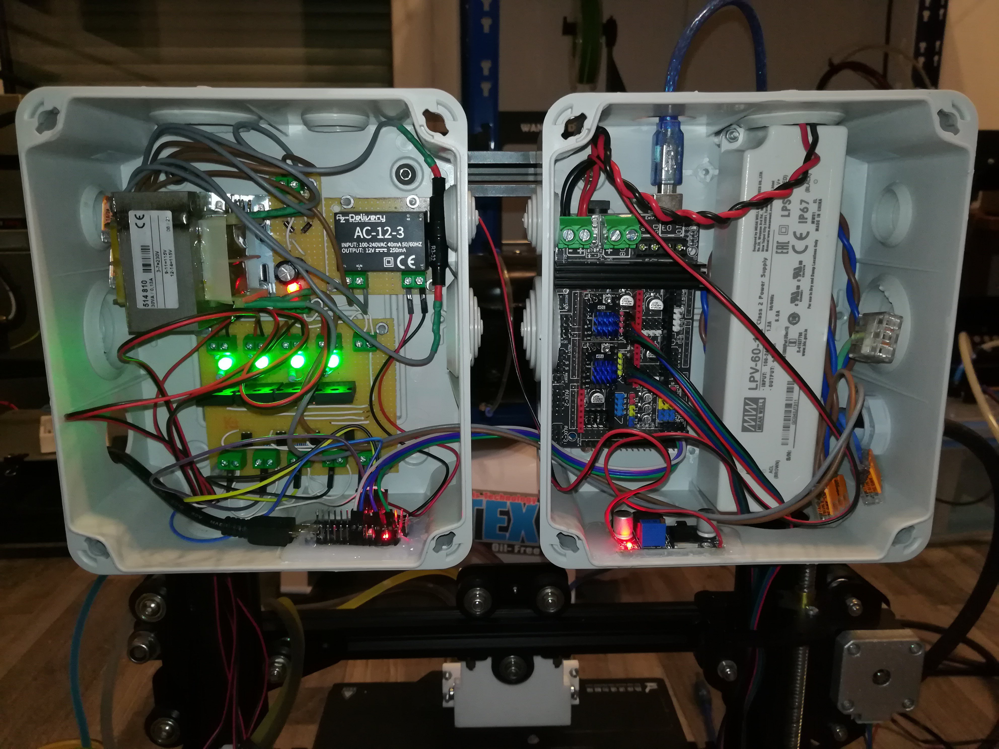
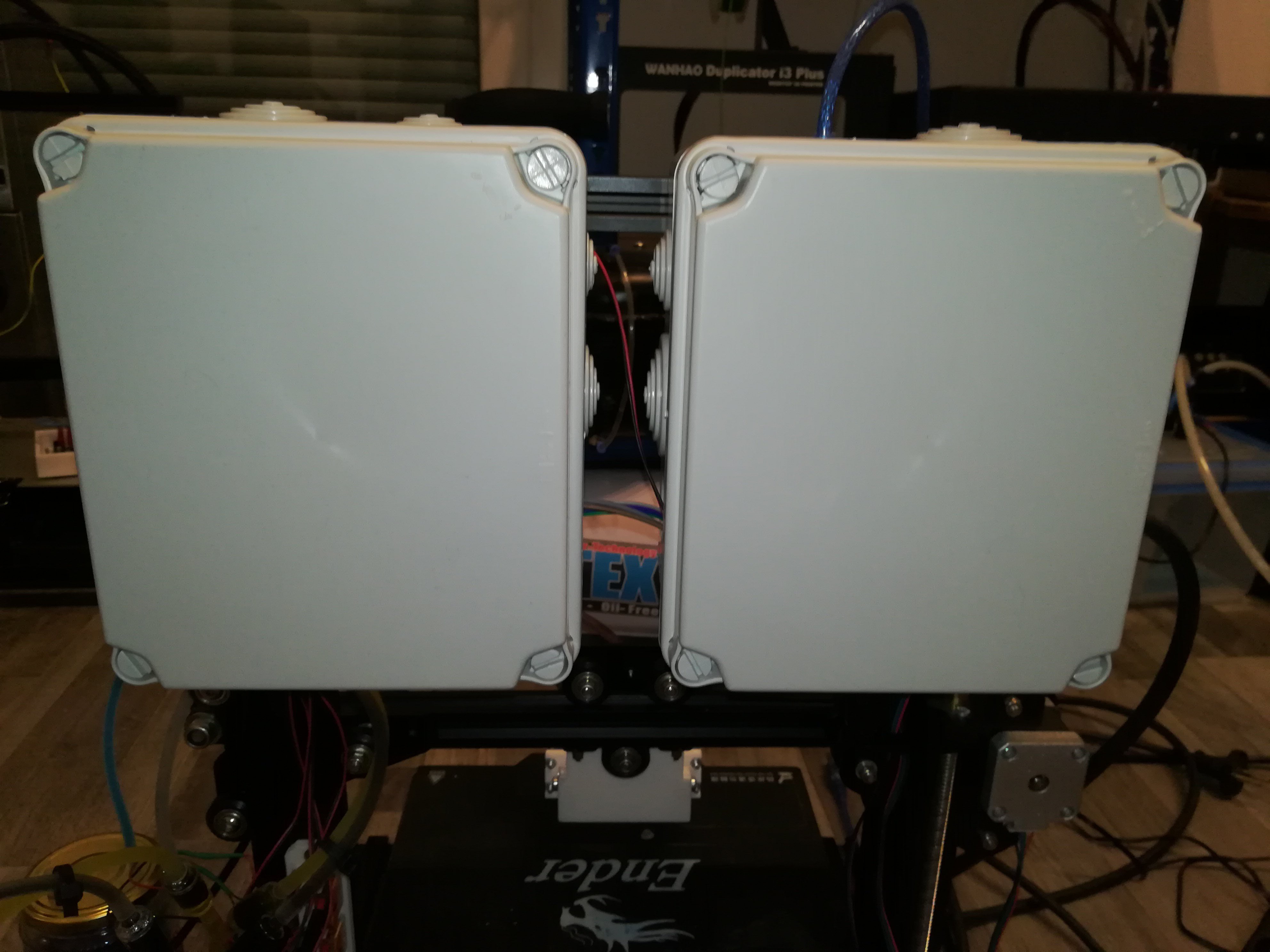
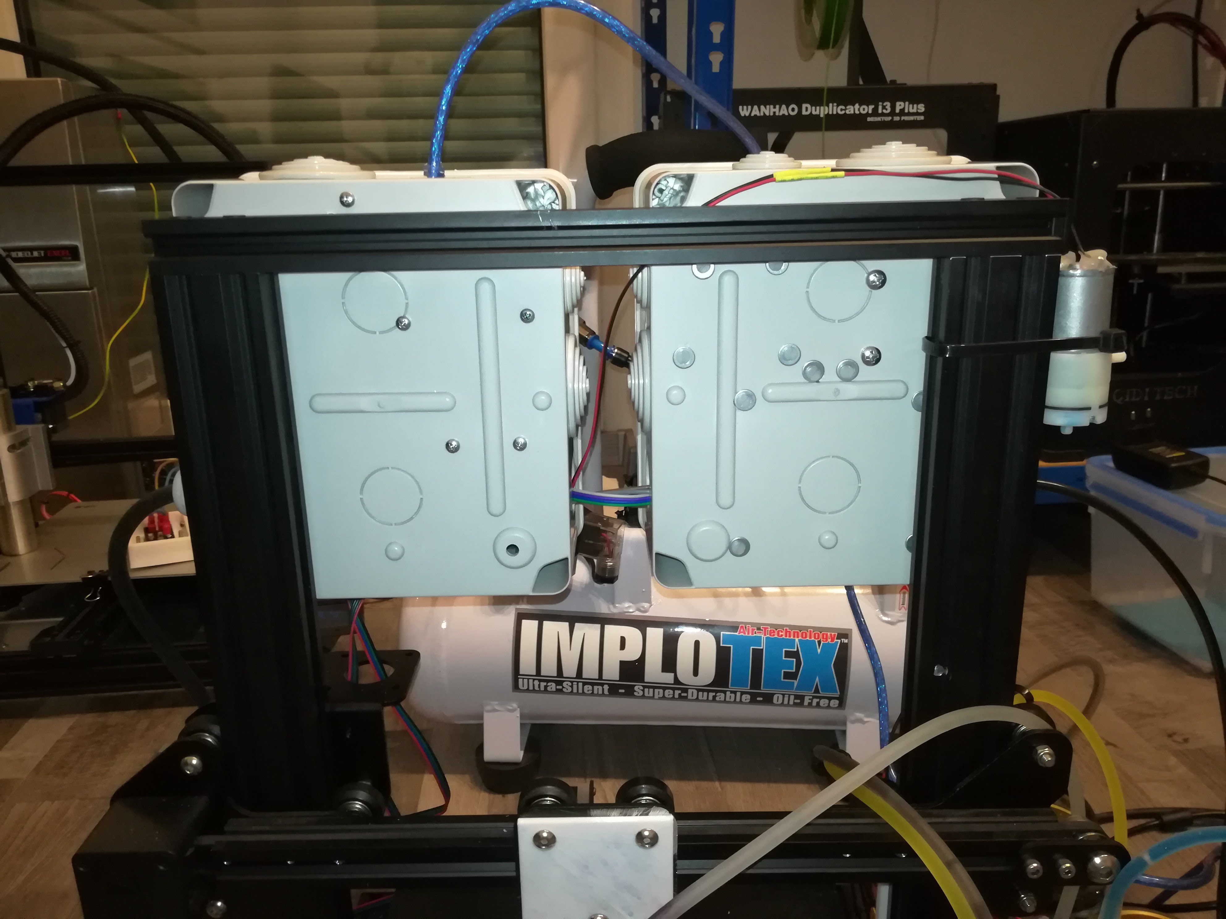
Placed the electronics in two boxes for a cleaner look.
Discussions
Become a Hackaday.io Member
Create an account to leave a comment. Already have an account? Log In.
To have "negative" polarity on piezo, you could drive them with H-bridge. For small drops - shorter pulses. Also if you just do pulses in one direction and then connect both ends to ground (maybe through small resistor to discharge piezo slowly), piezo will return to relaxed state, which should pump some ink back into chamber.
That's how commercial piezo printheads do it, there is fast pulse to eject drop and a little slower fall back to 0 to refill ink chambers for nozzles.
Are you sure? yes | no
Hi,
nice to hear from you again. Also thank you very much for recommending my Wire Printer Project. I didn't realize they wrote an article about it at the time.
Today I looked into building a H-bridge for 200V, but I could not find a way to do it, yet. I read about building one with only N-channel MOSFETs using the bootstrap method for driving the High side MOSFETs, but I read that would require a fast pwm to charge up the bootstrap capacitor which I think is not what I need for the piezo discs.
I got some P-channel MOSFETs, but I have no idea, how to drive the high side MOSFETs when using up to 200V.
I also read about building a H-bridge from DC SSRs.
I like your idea and will try it out.
Are you sure? yes | no
> but I read that would require a fast pwm to charge up the bootstrap capacitor
In such cases, search for mosfet driver chip. It's way easier to use them than doing it yourself.
http://www.farnell.com/datasheets/2124674.pdf
"The low-impedance, high-current driver outputs swings 1000 pF load 18V in 30 nsec. The unique current and voltage drive qualities make the TC426/TC427/TC428 ideal power MOSFET drivers, line drivers, and DC-to-DC converter building blocks."
By the way, recently a youtuber called Integza tried to make similar metal 3d printer, but from welding machine: https://www.youtube.com/watch?v=7w9hK8mh9-g
Are you sure? yes | no
I tried pulsing and discharging the piezo with an IRFP460 at 330VDC and a 470k ohm resistor across the piezo and it worked well.
Thank you, good idea :)
Maybe it could also work with half of the voltage, so that it can still be switched with the DC SSR.
I saw the video from Integza. It's cool, but he also could not get usable parts out of it. I also think the cost of the shielding gas will become very high after some time, so that some sort of reusing it could be useful.
I saw the youtuber Metal Matters is working on something that features recirculating shielding gas.
https://youtu.be/fmHF6QVSJRw
Are you sure? yes | no