Electroniclovers123
➢Step descriptions:
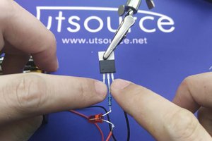
✦Step 1:-The middle pin of P55NF06 is welded together with the negative pole of an LED.

✦Step 2:-The left pin of P55NF06 and the 47K resistor are soldered together.

✦Step 3:-LED positive pole is soldered to a 220 ohm resistor.

✦Step 4:-The 4.47K resistor is soldered to one end of the 220 ohm resistor.

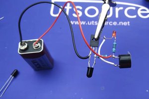
✦Step 5:-The positive pole of the 5.9v power supply is connected to the two resistors.

✦Step 6:-The negative pole of the power supply is connected to the right pin of P55NF06.

✦Step 7:-Connect a wire to the left and right sides of the P55NF06. Connect the copper wire in the middle.

✦Step 8:-When the copper wire is cut off. The alarm light is on.

Product list:
『P55NF06』 view more ⇒https://www.utsource.net/itm/p/1162660.html
『LED』 view more ⇒https://www.utsource.net/category/led-lighting-1.html
『47K resistor』 view more ⇒https://www.utsource.net/sch/47K%20resistor
『220ohm resistor』 view more ⇒https://www.utsource.net/sch/220%20resistor
『Power supply』 view more
『Wires』 view more
Video on Youtube: