 Yann Guidon / YGDES
This project is featured at the beginning of this video :
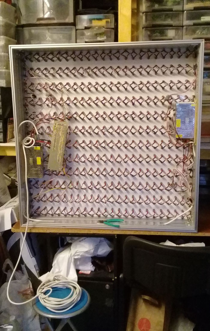
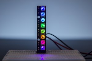
Two ping pong screens (24×24 RGB LED) display alternating videos in an endless loop. The circuits must be reliable, simple, cheap, and start immediately when powered up. The other constraint was the LED : due to sourcing issues, the array uses synchronous LEDs, whereas the #WizYasep can drive asynchronous LEDs only (so far). A custom solution was required...
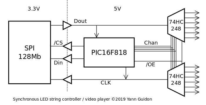
I came up with a pretty crazy system that was reduced to its essential components, using ideas I explored with Cheap bulk removable storage. The principle is simple : the output of the serial SPI Flash chip is almost directly sent to the data pin of the synchronous LED, while a microcontroller toggles the clock and other control signals.
That's simple, right ?
This is possible because very high density Flash chips have hit the market at great prices and a 128M bits BIOS chip can store many many frames :
1 frame = 8×3×24×24 = 13824 bits, or roughly 1/10000th of a 16MB Flash chip (9709 frames to be exact).
At 25 frames per second, the chip can store 388 seconds of uncompressed, raw video. That's more than 6 minutes.
At first I created a system with parallel reading of 8 SPI chips but I had to change the strategy in the middle of the project because the videos are short enough to fit into a single chip : about 6000 frames are used, well within the range. I also changed the number of output channels, from 8 to 12 and the TTL/buffers needed a revamp...
Of course there is the question of streaming the bitstream from a SD card. But that's probably too complicated for the 818. I suppose some people could try it though, if they have the proper libraries.
Logs:
1. The return of the PPS24
2. Radio synchronisation
.


 ACROBOTIC Industries
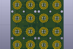
 Pierre-Loup M.
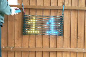
 LordGuilly
Reminds me a bit of the recent project by @bitluni. Looks good!