 Yann Guidon / YGDES
There has always been a requirement to synchronise both screens so they operate in a specific sequence. The rush of delivery in 2016 made me cut this corner...
Lately the 2nd screen (almost a clone loaded with a different video ) arrived so I could make them talk. And I think I nailed it, thanks to improvements in the available technology. I used a pair of BBC Micro:bit modules to talk over radio and deal with the protocol, to keep changes to a minimum for the main board. Having micropython and BlueTooth on board greatly eased the retrofit and kept costs low.
The main problem was "how do I connect to the main board with the least efforts ?"
I chose to use the serial programming/debug port, a personal connector with the 5 required pins to connect the Microchip ICD2 to the PIC16F818. It's a compromise because it makes debugging hard, as the PGC and PGC pins are shared with RB6 & RB7 port pins, but I just needed to make a small adapter board with male pins, and the rest of the main board is left untouched.
I fortunately have the backup of the source code of the 818 so I could slightly modify it. One board become the source/sender of a pulse and the other receives it. Then it's a matter of interfacing the Micro:Bit...
For the sender, I chose the Button_A pin, so I could emulate the pulses by hand for the small tests. There's a catch though : the Micro:Bit's button pin is pulled high to 3.3V though 10K, while the PIC has CMOS 5V output. The level shifter is as simple as a dumb SMD diode :-) RB7 can thus only pull down and the MicroBit is protected from higher voltages.
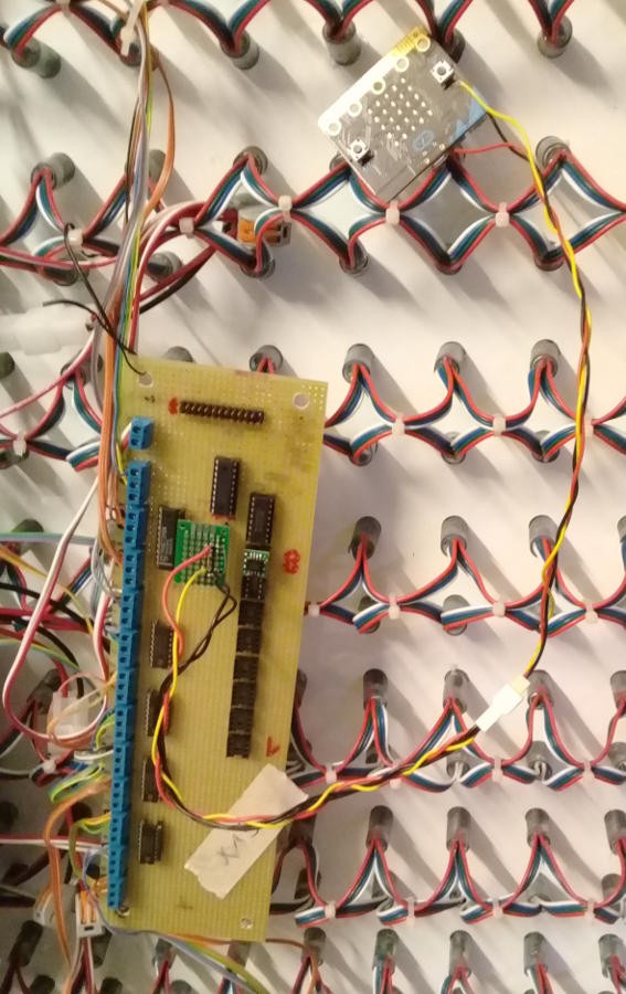
The ICD port provides 5V and GND and they are also brought to the Micro:Bit, using 3 wires. The Python source code is about 20 lines long, including radio configuration and detecting button presses and releases, though the modifications of the PIC asm code had to be more subtle...
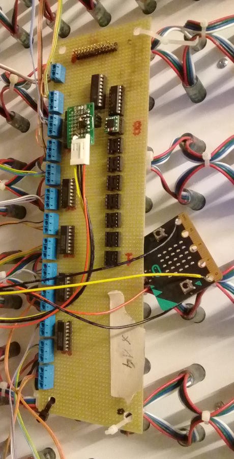
The receiver is barely more complex, with a dumb transistor inverter providing the level shifting. A BC550 and a pair of 10K resistors are enough to pull RB6 low when the Micro:bit's Pin0 goes high. I had to slightly modify the PIC's code as well to provide a nice asynchronous "reset" of the player. The Python code counts how many radio messages are received before sending a short pulse to the PIC, providing the desired sequence effect when both screens work together.
The ICD port was never intended as an extension port, since I planned a parallel system with IDC cables (that proved too cumbersome). Now there is no drift anymore, just as Fred Sapey Triomphe wanted back in the days. Thank you BBC and all the folks who built all these tools so we all can make cheap and quick hacks ;-)
Discussions
Become a Hackaday.io Member
Create an account to leave a comment. Already have an account? Log In.