 Thomas
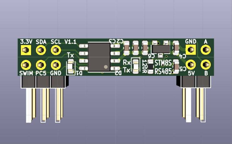
When doing hand soldering I learned "first hand" that the orientation of 0603 components matters, and consequently I worked a bit on the component placement of the tiny STM8S001J3RS485 PCB. Using 8 mil signal track width, 6 mil clearance and 10 mil via drills made it a lot easier compared to sticking with the KiCad defaults. The power supply now forms a rail from left to right, switching the side of the PCB about in he middle.
The text on the silcscreen is friendlier, too (even if they make good use of the 400DPI silcscreen that @oshpark provides (i.e. the print is tiny):
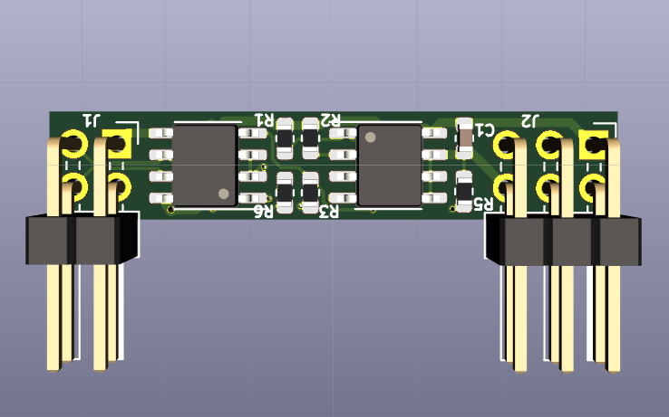
The 0603 components on the back side now are also easier to populate.
The new board is available on the @oshpark shared project pages, and the GitHub repo has been updated.
Discussions
Become a Hackaday.io Member
Create an account to leave a comment. Already have an account? Log In.