 Paul Burford
After a lot of designing, redesigning, scrapping and discovery of things I didn't know existed, the plan morphed into:
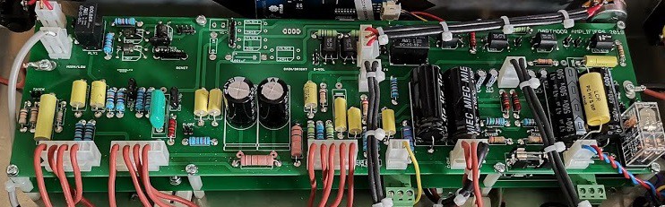
An all-in-one guitar amplifier based on the legendary Marshall 2204.
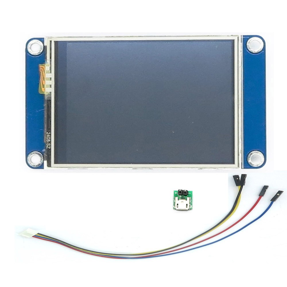
This was to be controllable by a touch screen.
It was to have space for twenty presets.
It was to have midi capability.
It was to have a zero loss effects loop.
It was to be programmable using an android app.


 Lithium ION
 Sagar 001
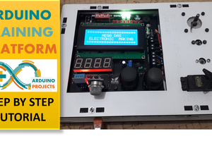
 DIY GUY Chris
 Peter G
I'm new to Nextion touch screens and found this project, very nice idea. I don't find any info on the nextion programming or arduino here. Is this a project in development or are the files for the micros somewhere to try.