Paul Burford
-
PWM Pain
09/08/2019 at 16:06 • 0 commentsAfter completion of the PCBs, the main problem I encountered was the Arduino's use of PWM. At stock operating frequency / bit level there just wasn't the detail needed to provide adequate steps for the optoisolator to adjust it's resistance smoothly. 256 steps in itself was enough but the optoisolators aren't linear. To combat this, I tried changing the resolution of the PWM to it's maximum of 65535 steps or 16 bits (for the applicable timers). This gave more than enough steps to fake linearity with the optoisolators but created a tremolous warbling sound when guitar was played. More research led me to deduce that an increase in the bit rate decreased the operating frequency to the point where it could be heard in the guitar sound. A compromise needed to be reached and was found at a PWM rate of 749... high enough to fake some sense of linearity but low enough not to affect the guitar tone. The code used (repeated for all applicable timers) was...
TCCR1A=0;
TCCR1A |= (1 << WGM11);
TCCR1B |= (1 << WGM12) | (1 << WGM13) | (1 << CS10);
ICR1=749;Finally, the optoisolators and Arduino were doing their job.
-
Second PCB
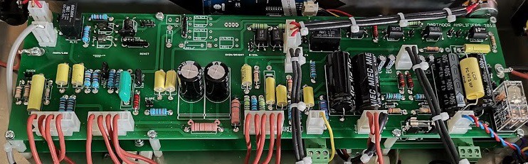
09/08/2019 at 15:51 • 0 commentsThe second PCB was to house the Arduino, the FX loop and the gain pot optoisolators. I decided to mount it directly underneath the main PCB, 20mm apart using spacers. Any connections between the two would be made using 0.1" spaced double ended headers. After arrival from China, the population of the second PCB began and the two PCB boards were mated together.
![]()
The three empty optosolator component spaces can be seen at the top of the PCB. They were now relocated to the lower PCB resulting in a much lower noise floor.
-
It's not as easy as it looks!
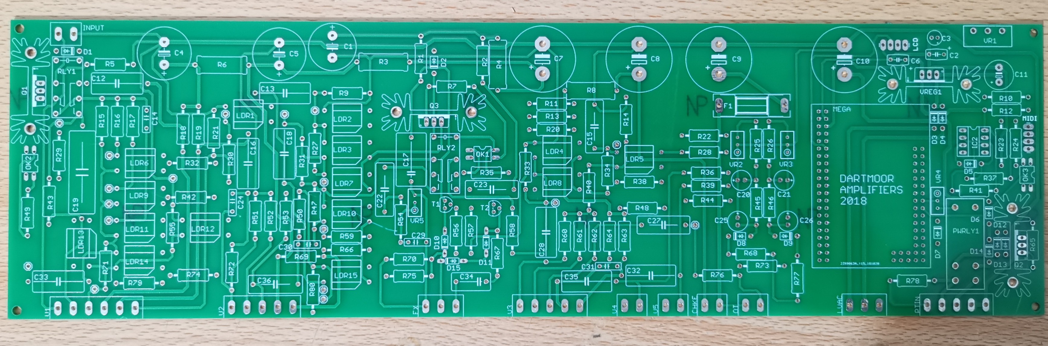
09/08/2019 at 15:45 • 0 commentsIt took about three months to design my first PCB. I made the fatal design error of trying to fit it all into the smallest space possible. So, I designed a single PCB using the few rules that I knew and I placed the order from JLC in China.
![]()
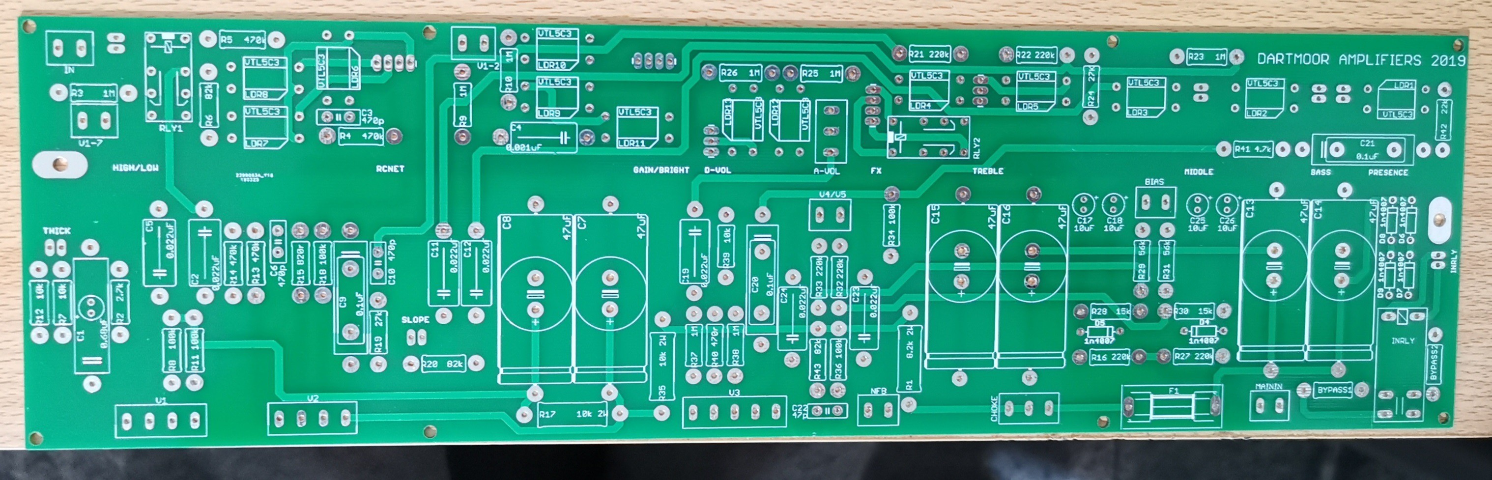
I fully populated the board even though the programming of the arduino was far from finished. The interference from the Arduino was huge. The hum, or should I say buzz, was like a chainsaw. Whilst the amplifier itself was working, there was no way that I could live with the background noise. I went back to the drawing board and redesigned the PCB. This time I didn't include the wiring for the Arduino. I was determined just to get the amplifier side of things working. PCB rev 2 turned up a month later...
![]()
The bottom half of this PCB was similar in layout to the Marshall JCM800 PCB, albeit with a lot of spaces for optoisolators instead of wires going to potentiometers. I started off with pots loose on floating wires. The amp breathed it's first breath... but optoisolators replacing the gain pot would have to be moved. They were creating a lot of hum. Relocating them an inch away from their current location (in any direction!) solved that problem. Time to think about the PCB that would house the Arduino. Perhaps it could house the gain pot optoisolators as well.
-
One step forward, two steps back
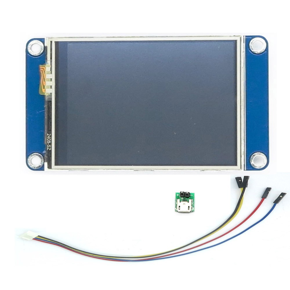
09/08/2019 at 15:26 • 0 commentsStage two: I decided that I wasn't happy with the LCD screen. It looked so 80's! So, I researched touch screens and came across the Nextion from ITead.
![]()
As another big bonus, I found that this had a functional editor and meant that I could get rid of any tactile buttons that I was going to have to use if I had stuck with the LCD screen. Programming of the Uno to accept commands from the Nextion began, until the Uno ran out of memory. Research led me to find the mega 2560 pro (embed) from robotdyn. A small footprinted Arduino Mega.
![]()
For every step forward came a step back. The digital potentiometers had to be replaced with optoisolators and it was becoming increasingly obvious that tagboard, breadboard, turretboard and point-to-point were not viable options. It was time to learn how to use Eagle to design PCBs.
-
Initial ideas... and stumbling blocks
09/08/2019 at 15:16 • 0 commentsInitial design ideas took six months and initially I stupidly thought that I could create the amp on tag board or point-to-point like most of my other amps. I started with the Uno that I initially bought along with a 4x20 LCD display and tried looking at digital potentiometers to replace the traditional pots. This threw up more problems than I thought it would. The Uno didn't have enough PWM enabled pins, so I bought a 16 bit breakout board. This was successful but the digital pots were fiddly as they were SMD. It all looked promising until I realised that most of the signal voltages in a valve amp are a lot higher than that which can be handled by digital pots. Back to the drawing board. The picture shows my first breadboarded tone stack using a digital pot and three Silonex NSL-32.
![]()
Arduino Nextion Android Midi Valve Guitar Amp
Control a Marshall JCM800 2204 style guitar amp using touch screens, midi foot pedals and an Android App