Close
0%
0%

SimpleUI-Logger

A tiny, simple voltage/current logger with USB for electronics hobbyist

Similar projects worth following
405 views
0 followers
A tiny, simple voltage/current logger with USB for electronics hobbyist, and for fun

This toy is designed to meet the following specifications:
(actually not fully achieved with the current version)

Voltage Measurement:
-Range: 10V, 10mV resolution, +/-(1% + 10mV) accuracy

Current Measurement:
-Range: 500mA, 1mA resolution, +/-(1% + 1mA) accuracy
-Range: 5mA, 10uA resolution, +/-(1% + 10uA) accuracy

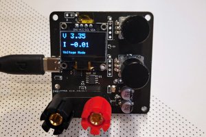
Currently not fully tested, but works by slowly varying voltage and current. Might develop a new version to reduce cost.

Known design failures and modifications:
1.  Remove R35, since it introduces leakage current in 5mA range
2. Add 1uF 0603 MLCC parallel to C12 to reduce ADC noise
3. Remove R3, and solder R4 for booting from Flash
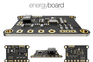
PCB with KiCAD 5
A simple GUI is designed with Qt
Firmware with STM32CubeIDE

simpleUI_Logger_121019.bin

Over-current and over-range detection with integrated fast comparator

octet-stream - 32.04 kB - 10/12/2019 at 11:39

Download

Comma-Separated Values - 16.29 kB - 09/14/2019 at 09:14

Download

octet-stream - 31.27 kB - 09/14/2019 at 09:13

Download

simpleUI_Logger_ver0rev1.zip

KiCAD PCB project, the ver0 rev1, not fully tested

x-zip-compressed - 215.55 kB - 09/13/2019 at 20:36

Download

case_v0.stl

A simple case with 3D printing to keep the board warm

Standard Tesselated Geometry - 42.07 kB - 09/13/2019 at 14:58

Download

View all 6 files

  • New features implemented

    Shuo Cao10/12/2019 at 11:29 0 comments

    * Switch off 10ohm shunt resistor with integrated fast comparator interrupt, when current exceeds 5mA range. Faster response to over-range, avoid significant voltage drop due to 10ohm shunt resistor

    * Switch off MOSFET and latched when over-current detected with integrated fast comparator. Threshold defined by a resistor voltage divider. However usable current range reduced to less than 500mA due to relatively high gain 64.9. Will be changed to 59 as with 5mA range to allow current higher than 500mA in next version.

  • Memo

    Shuo Cao09/14/2019 at 08:09 0 comments

    Version 0, revision 1

    Parameters to test:

    • Linearity of 10V voltage measurement range
    • Linearity of 500mA current measurement range
    • Linearity of 5mA current measurement range

    Features to implement:

    • Use built-in low power comparator to switch current range
    • Use built-in low power comparator to detect over current
    • DC offset storation and calibration

    Hardware modification to test for new version:

    • Easy selectable boot mode with jumper
    • Drive LED directly with GPIO, without transistor

View all 2 project logs

  • 1
    PCB

    This device has a 4-layer PCB, which is 6x4cm in size. I've ordered 5 pieces on Allpcb, which costed 33 USD and 21 USD for shipping to Germany. The price is okay for prototyping, since home-made is no more an option and local PCB manufacturer require 200 Euro for that thing. Actually I have other PCBs to order the same time, so the shipping cost is also acceptable.

    For 50 pieces of PCB, the average cost per PCB is only 1.3USD at Allpcb, so it's really a matter of prototype or production.

  • 2
    BOM

    There are approximately 40 different components and 90 parts on the PCB. The types of the components will be reduced if new version is to design. I've got most of them already in my boxes at home, after long time collection for different projects. However most of them could be ordered at Mouser, 90 percent, which still sells to private customers in Germany. The BOM cost is for the current version still high, if only 1 piece is to build. For 1 piece they cost about 14 Euro for 93% of the BOM at Mouser.

    The BOM list can be found in the uploaded files.

  • 3
    PCBA

    Soldering of SMD components at home requires patience. If one is skilled on soldering, then the only difficulty on this board is the transistor, which is quite small and has a thermal pad underneath. I would like to replace this component with a SOT package for new version.

    A magnifier is quite helpful. Most resistors and capacitors have 0603 package, which are still ok for hand soldering under magnifier.

    The current version has two-side placement due to size limit. However it would be possible to place all components on top side for the new version, leaving only some through hole components.

View all 8 instructions

Enjoy this project?

Share

Discussions

Similar Projects

Does this project spark your interest?

Become a member to follow this project and never miss any updates