 Frédéric Druppel
Build logs :
- Introduction
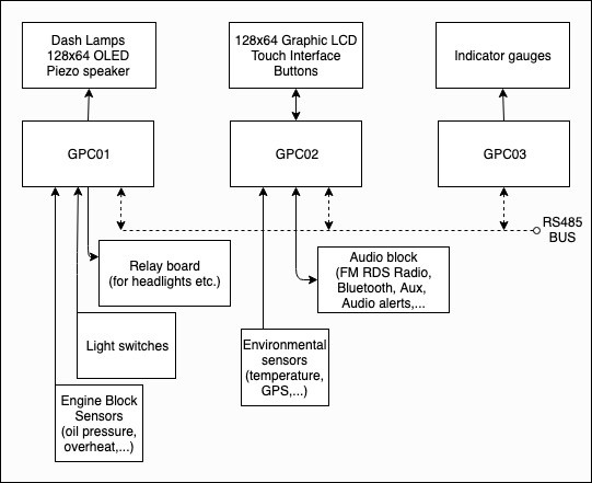
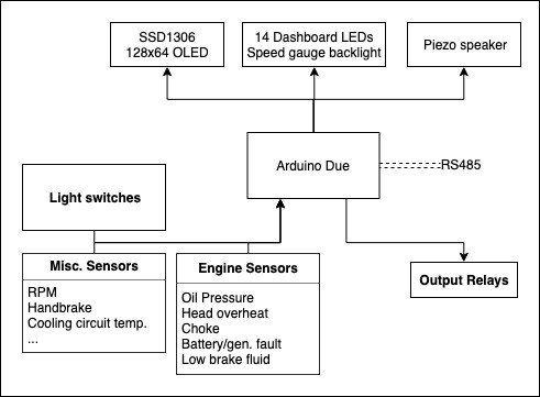
- Function Diagrams
- Miscellaneous bits
- GPC01
- GPC02
- GPC03
- I've changed my mind...
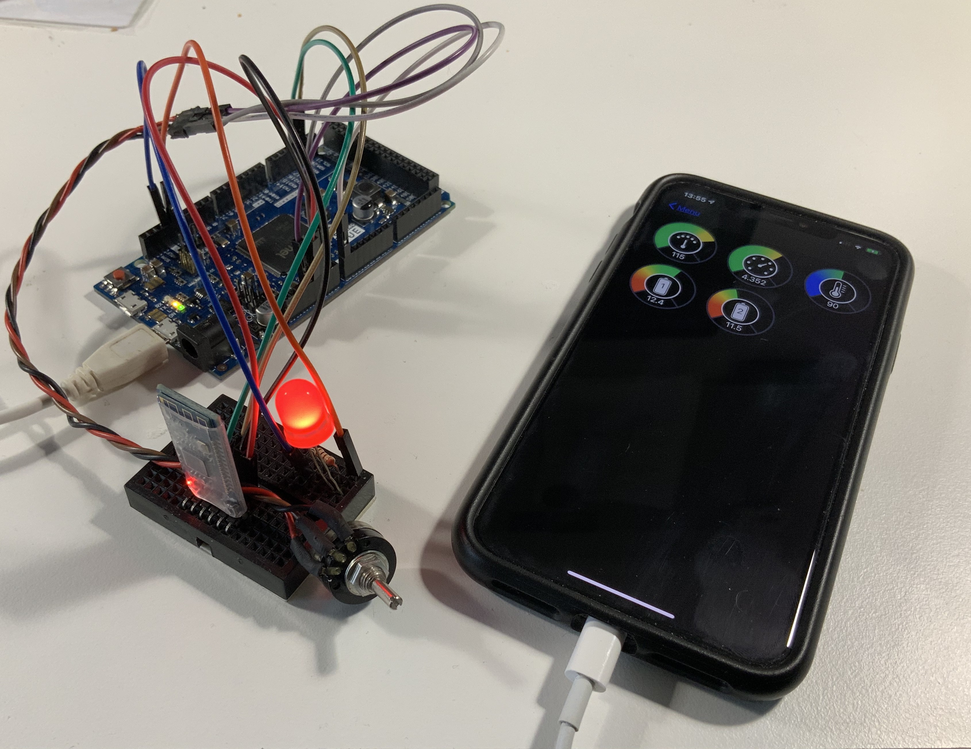
- ... And I've built an app.
•
Progress :
- General Purpose Computers :
- GPC01 Dev progress : Almost done, need to improve RPM reading and implement CAN bus.
- GPC02 Dev Progress : Back to the drawing board
- GPC03 Dev Progress : Not started, questioning it's usefulness
- Other Modules :
- Electric Power Distribution : Planning started, waiting for the components to arrive by mail.
- Improved Ignition coil : Build done, need more testing and build log.
Status :
Paused due to finals; will resume shortly.

 dennis
 davedarko
 daniel.bryand
 Dominic