 Frédéric Druppel
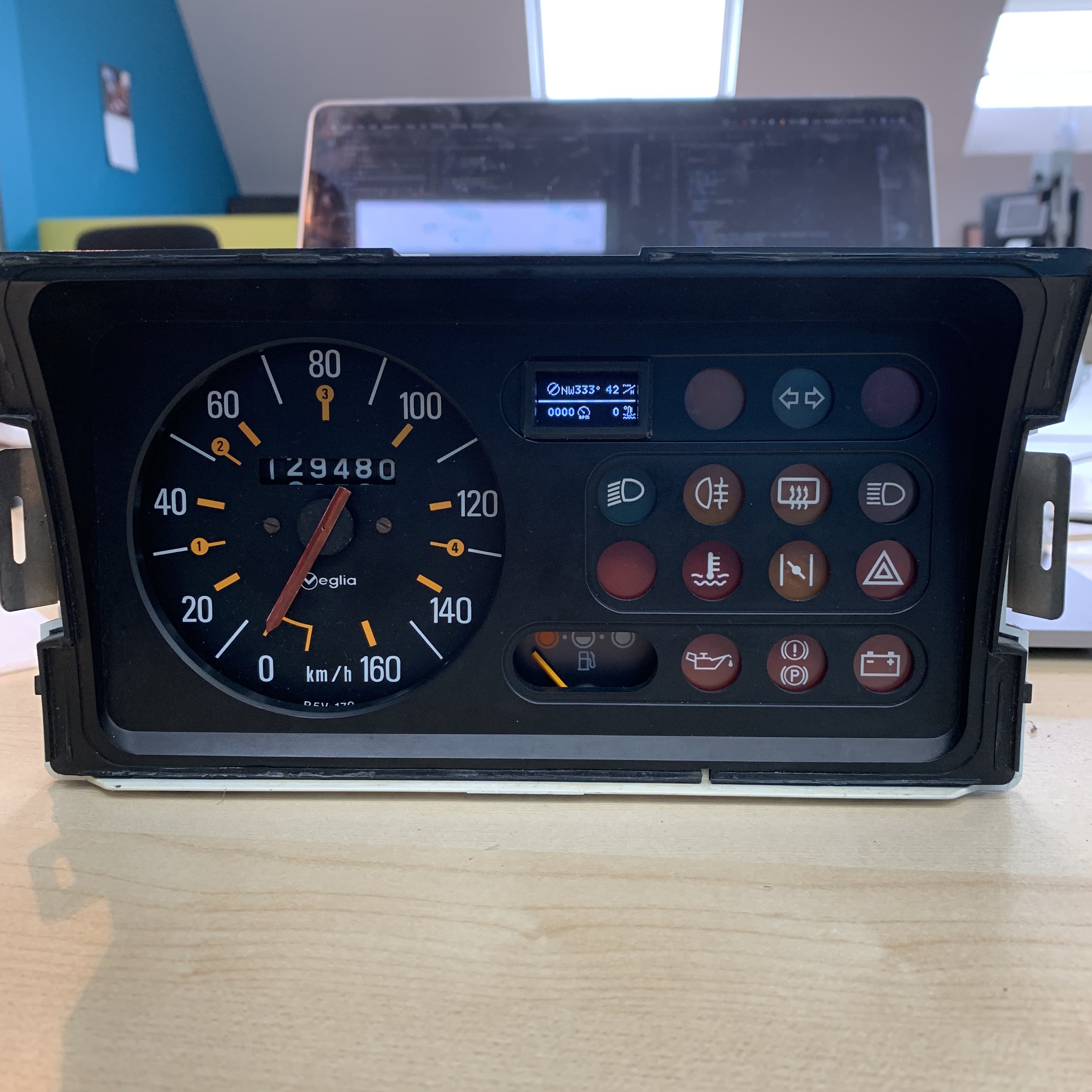
This is the board computer that controls all the lights, and monitors the different engine fault sensors. Now you may wonder why I’m going through an Arduino just to control lights with a simple switch, and there is no real reason why I’m doing so, other than custom functionalities ! For example, I can precisely control the blink rate of the turn lights (which you should definitely use when turning BTW), or I can put a « Master test switch » to turn all of the lights on for visual inspection.
But, of course, it has to be very reliable; I don’t think it would be pleasant is my headlights turn off randomly at night while I’m driving because I forgot to break a loop... So there’s a lot of thorough testing going on !
•
You may have noticed a small 128x64 OLED screen embedded; This screen, when everything is OK (e.g. when there’s no fault sensor triggered), displays useful information like engine RPM, cooling fluid temperature, and GPS Speed&Heading from GPC02.
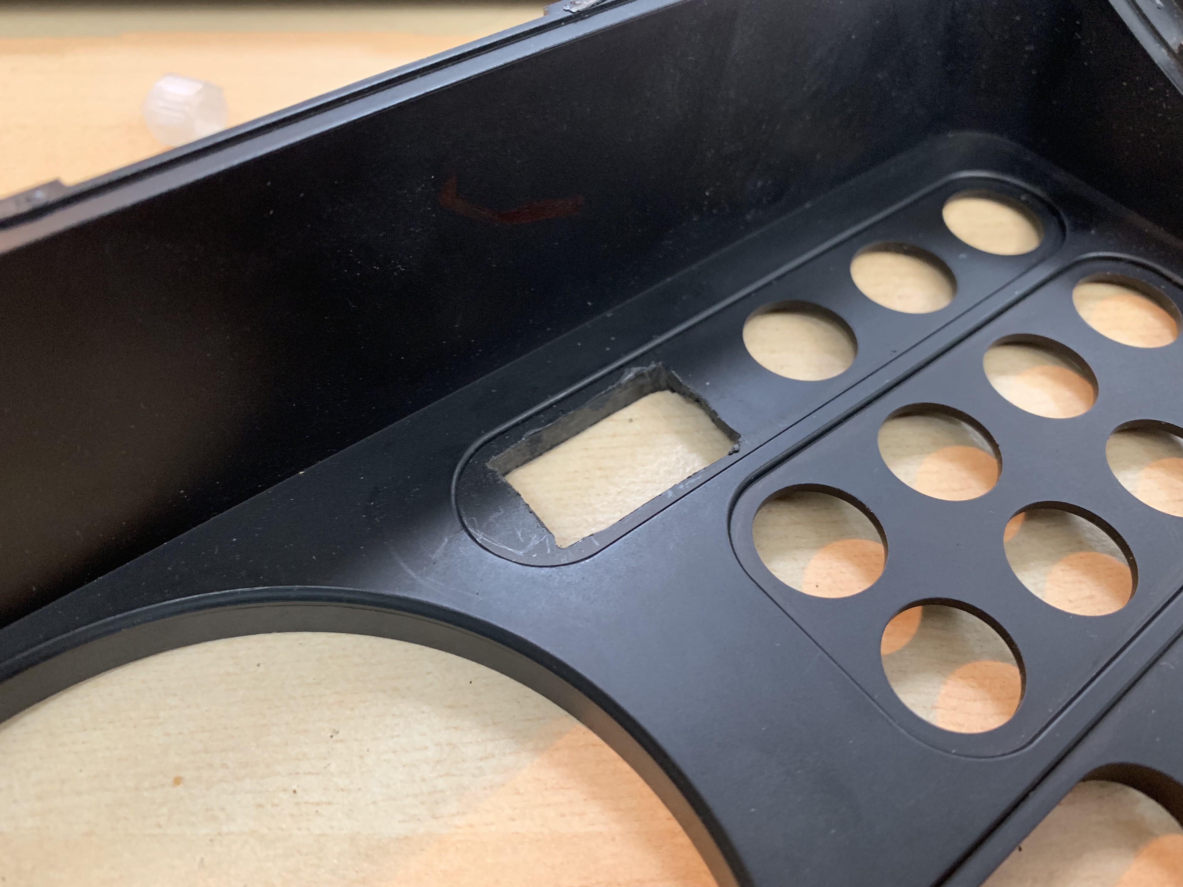
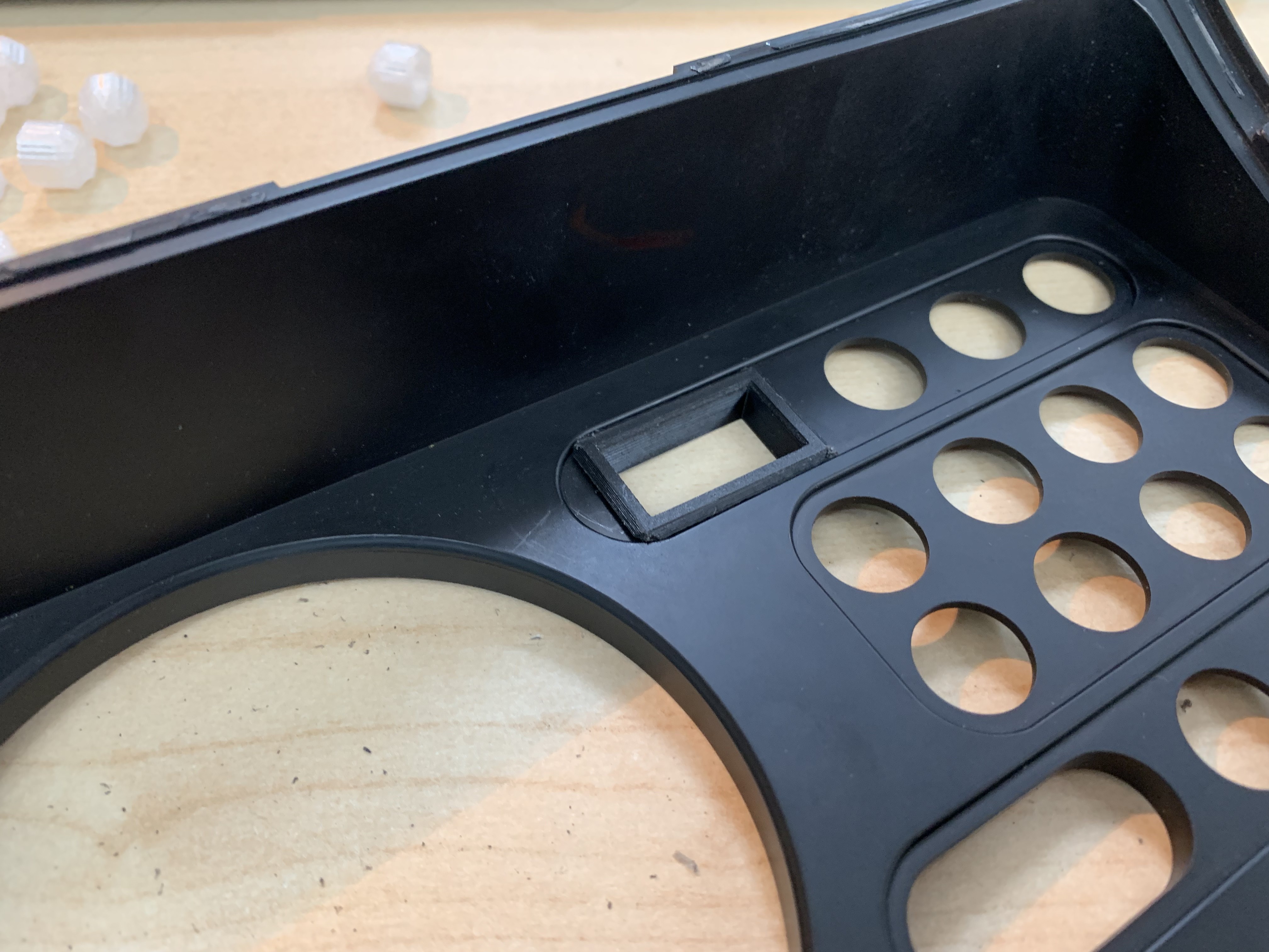
I made a hole in the original dashboard, and printed a little fame to make it look nicer :
This display also gives detailed error messages when a sensor is triggered. Here are the different logos I made for it :
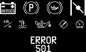
Those where drawn in Adobe Photoshop pixel by pixel, and converted to c++ arrays with LCDAssistant.exe, so I didn’t have to convert by hand all 8192 pixels of some logos.
As you can see, there are 128x64 (shrunken down to 64x32 above), 32x32, 16x32, 16x16, and even 16x8/8x16 logos.
The only 128x64 logo is for the "ERROR 501" screen; this one shouldn't ever show up, unless I did something wrong in my display routine and the display I'm trying to, well, display, doesn't exist.
The 32x32 logos are on the upper row : battery, handbrake, low brake fluid and choke.
The 16x32 and 16x16 logos are on the second row : km/h (speed), cooling circuit temp, low oil pressure (16x32), compass (heading) and engine RPM.
Now the 8x16 and 16x8 logos; those are actually the "P" and "Genie lamp" logo inside the bigger 32x32 brake logo. In order to save on code space, when the Arduino has to draw the "handbrake" or "low brake fluid" logo, it first draws the background (e.g. the circle with two parenthesises (32x32)), then in the middle of that the "P" or "Genie lamp", whichever is needed. This means that I only need to store one 32x32 logo array, and two smaller 16x8/8x16 logo arrays (every saved byte counts !).
•
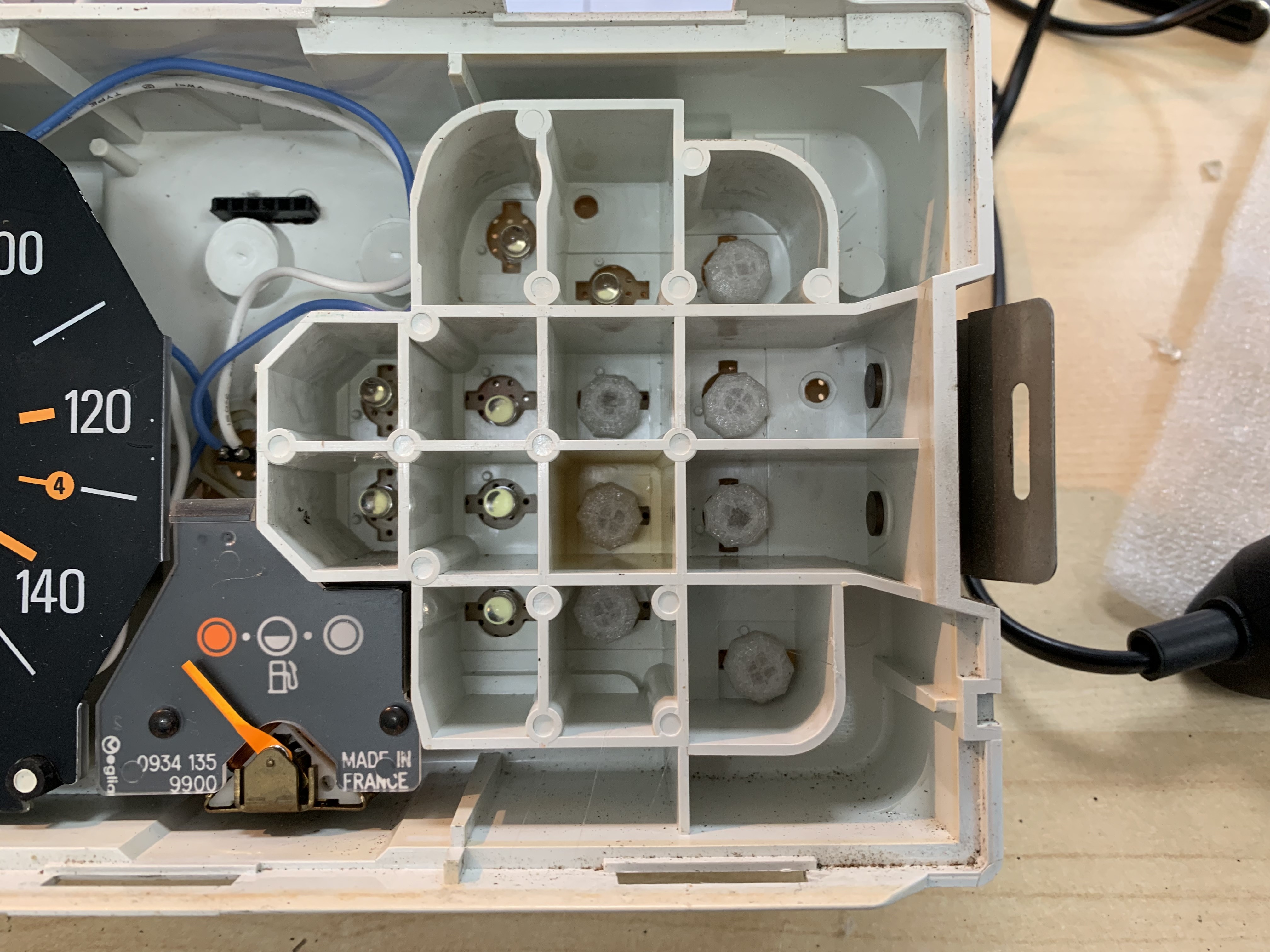
All the original light bulbs where replaced with white LEDs with 3D Printed PETG diffusers. Each LEDs is controlled by an individual pin on the Arduino Due. You may also notice a white and a blue cable, right above a 6pin connector; the two wires are for the speed gauge backlight, and the 6p connector is for the OLED screen and the piezo speaker. The piezo was put right there so I can actually hear it above all the engine noise.
[Remaining info coming soon]
Discussions
Become a Hackaday.io Member
Create an account to leave a comment. Already have an account? Log In.