 ensgoldmine
This device is a simple but practical way to visualize and measure various small magnetic fields, as well as roughly measuring the current flow through wires.
Typically current is measured using "Shunt Resistor's" in series with the desired PCB trace or “Split Clamp” device, or a typical multimeter in ammeter mode. Whereas this is suitable for individual wires, it can be a pain to implement on a PCB, as both methods involve physically breaking the circuit in order in order to perform these measurements. Physically altering the circuit introduces unwanted circuit impedance when a Shunt Resistor or jumper wire is added in series with the existing trace.
Using the DRV425 IC by Texas Instruments we can probe a PCB track and the current flowing through the copper trace can be observed and measured. Using Ampere's Law, which states that a current carrying wire produces a magnetic field being proportional to the current flow.
The field sensor must maintain the shortest possible distance from the PCB trace as possible; as Ampere's Law states this Magnetic Field exponentially decreases with the square of distance (to a first order approximation) as described by Ampere’s law for current carrying wires. The integrated fluxgate magnetometer sensor is manufactured into the silicon dye, along with all necessary amplifiers and circuitry.
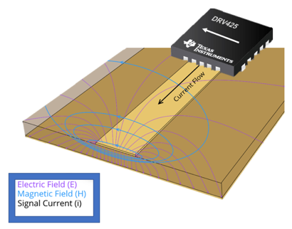
Figure 1: Diagram of DRV425 measuring the magnetic field of PCB trace.
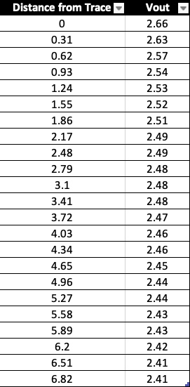
Figure 2: Table of DRV425 measuring the magnetic field of PCB trace at variable distances in millimeters.
As you can see from the above table. If the probe tip is 1mm away from the trace being measured we can see that there is a roughly 50% loss in the measured field strength.
Fluxgates operate on Faraday's principle of electromagnetic induction. Current is induced by the primary and secondary coil(s) being driven in and out of saturation in order to achieve an equilibrium. When an outside magnetic field is introduced to this system in equilibrium, the net change in flux will cause the inductive coils to produce current due to Faraday’s law. This current, while small, can be amplified and measured in order to extrapolate external field strengths.
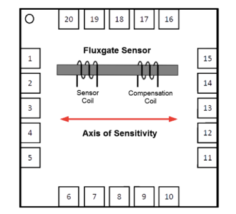
Figure 3: DRV425 Integrated Circuit showing internal fluxgate
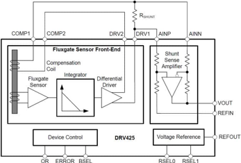
Figure 4: Simplified Block Diagram for DRV425 Integrated Circuit
Texas instruments supplies a formula that allows the user to extrapolate the output of the sensor in Volts, to a readable magnetic field value in Tesla. The first element is the gain of the compensation coil which is defined as “The compensation current is proportional to the external magnetic field and its value is 12.2 .” [1] This compensation current generates a voltage drop across an external shunt resistor, , shown in figure 1. “An integrated difference amplifier with a fixed gain of 4 measures this voltage and generates an output voltage that is referenced to REFIN and is proportional to the magnetic field.” [1] The value of the output voltage at the pin (VOUT) is calculated using Equation 1:

The Arduino Due is the best choice of micro-controller over the UNO, Leonardo or other cost comparative devices as we can achieve the best possible sampling rate and resolution. The Arduino DUE has a 12-bit integrated ADC (Analog to Digital Converter). This eliminates the need for an external ADC, and increases measurement accuracy. Typical cheap ADC's found on Amazon, Ebay, ADAfruit ect. use I2C serial communication which unnecessarily slows the rate at which we can sample. The fastest external ADC I found could sample at 188.9K Samples per Second at 12-bit resolution, which is almost the same price as the DUE with less than 1/5th of the possible sampling rate.
By setting the Arduino DUE to "free-running" mode we can achieve...
Read more »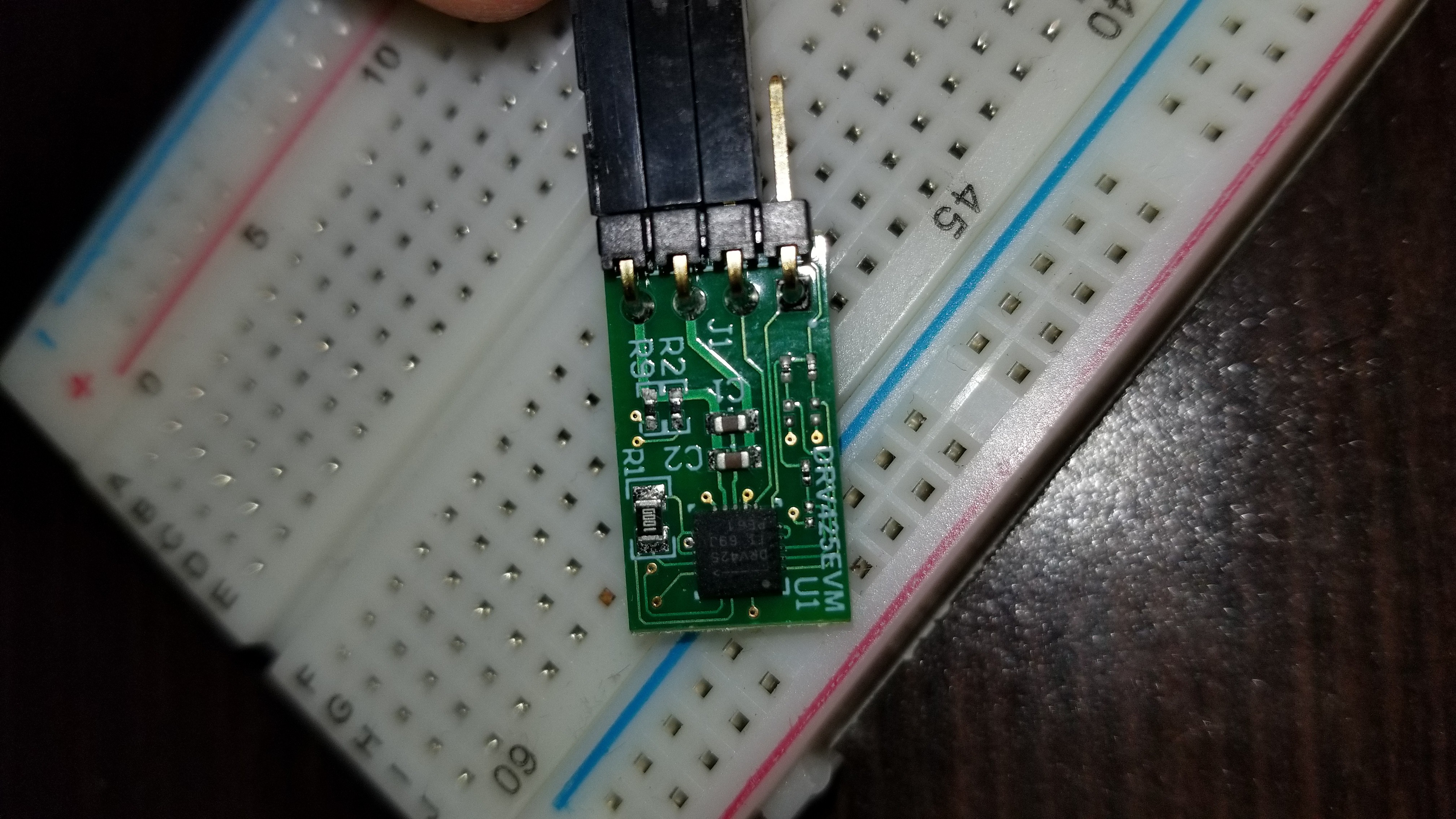


 Lithium ION
 mbsg99
 mircemk
 Sagar 001
thanks for the awesome project , where should i connect the shunt resistor ?
and which pins to solder on DRV425 module ?