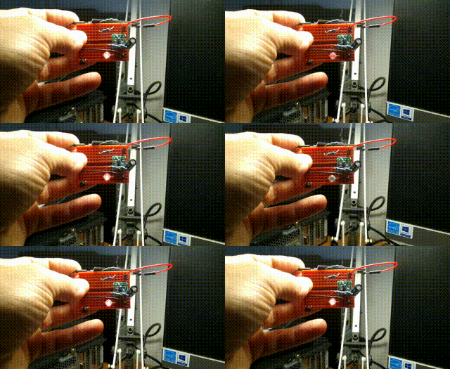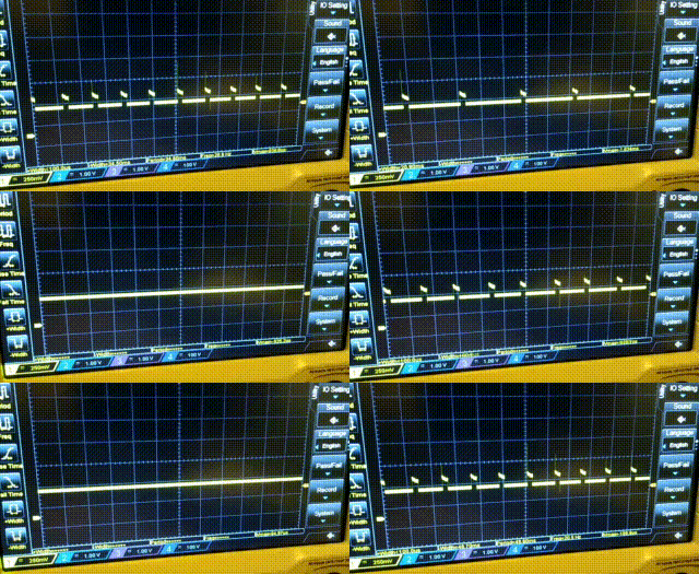
Here's a basic breadboard test of the pulsed discharge of the buffer capacitor. The variation in flash rate/duty is due to the time it takes to recover to a certain voltage, before repeating the discharge down to a threshold voltage, a few 100mV below the recovery voltage.

I then replaced the LED with a 1.5F capacitor in series with a 47ohm resistor (for current limiting while I still work all this out). You can see the duty varying to meet a changing brightness on the solar PV cell and the recovery time to recharge the buffer capacitor increasing (represented by the 0V spaces between pulses).
Apart from the shenanigans with diodes to prevent backfeed at no-voltage from the solar cell, I think we're ready to try a basic MPPT.
My thoughts are to take a reading of the initial voltage, so we know where we're aiming for during recovery. Then discharge until we're close to the supply minimum of 1.8V for the ATtiny402. Take a timestamp and then record the time it takes to recover every, say, 200mV. Run the calcs on the power as per the previous log and select the best range of voltages to swing the buffer between. Run the pulses at this voltage range for a given period (10 seconds, a minute?) and then repeat the full discharge/recover time profiling and calculate the new MPP.
 Simon Merrett
Discussions
Become a Hackaday.io Member
Create an account to leave a comment. Already have an account? Log In.
So just to update, the pulses you can see in the GIF above are quite pronounced and I wasn't able to take the overall capacitor voltage above around 1.7V. I realised that I had purely between switching the GPIO HIGH to charge the supercap and then LOW at the end, which was then sinking current back into the microcontroller GPIO (I think).
I think I have fixed this by setting the supercapacitor GPIO to input when I want to end the discharge of the buffer capacitor into the supercapacitor. It is now charging up to 3.33V on a little solar cell under my desk lamp. I missed the point at which the indicator LED stopped flashing - presumably when the buffer cap never reached 200 or 300mV below the starting voltage, the GPIO stayed open. Which is what we want!
Are you sure? yes | no