 Simon Merrett
So the previous circuit I logged was looking at discharging the buffer capacitor within a voltage range that would then be matched to the MPP. @crun pointed out the issues with this: firstly, when you have low light levels you have low voltage across the pv panel - this isn't useful if your storage medium (supercapacitor) is already above this potential. Secondly, if you have bright conditions, you can just run at lower efficiency, so why chase the MPP?
Apart from the initially unsuccessful foray into switched boost circuitry with inductors I mentioned in the most recent log, I wondered if a charge pump might function as a way to make use of the lower voltages. So here's the idea:
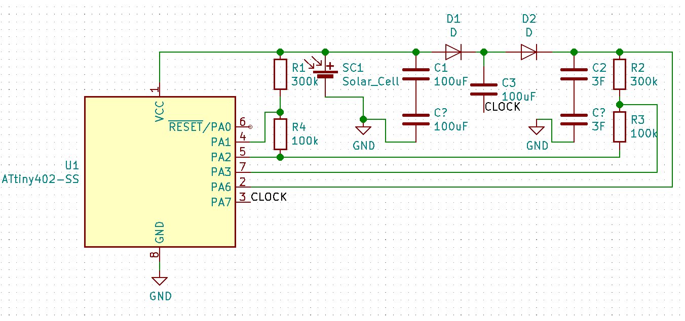
The main differences from the previous scheme are the diodes and capacitors to implement the voltage "doubler" circuit, including another voltage divider to determine the voltage across the supercapacitor.
Something worth noting is that in the overall design I want to run a PIR sensor and LEDs, to provide some motion-triggered low level lighting. With decent supercapacitors and a PV panel, the cost of the ATtiny402 microcontroller is no longer a dominant part of the BoM, and for this reason, I decided that there would be a separate microcontroller for the charging circuit and another one for the sensing/lighting circuit. This also means I can avoid using the untested arrangement of diodes to supply the microcontroller from both the supercapacitor and the photovoltaic panel.
Yes, charge pumps are theoretically less efficient, not to mention "real world" inefficient than inductor based voltage boosters, in the cases I have read about. For my case though, they may make sense. Even if you ignore my inability to build a decent inductor-based boost circuit. There are losses in both the diodes but in our case, this is a bit of an advantage, as twice the solar panel voltage would take us over the maximum voltage of the microcontroller that's going to control the lighting.
I implemented the basic charge pump with two normal silicon diodes because after my pain with the #Yapolamp supercapacitor leakage, I am not bothering with Schottkys for this until I really want to optimise. I didn't breadboard the voltage dividers but you will notice that one end is connected to a GPIO so that I can prevent them from leaking current when not in use.
Although I don't have a direct comparison, the BEST boosted voltage my inductor circuit topped out at was 4.26 volts under an LED torch. Because I hadn't implemented any voltage sensing on that design, as soon as the light dropped slightly, the voltage stored on the capacitor started dropping. Whereas on the charge pump circuit, I managed a respectable 5.2V, with a 1.5F supercapacitor store by the window on a rainy day in UK. I'm currently testing it under the same LED torch as I used for the inductor-based boost circuit, just to check there was rough parity.
So charge pumps are less efficient but they have an advantage - I have managed to make a circuit that works with them! In the real-world test of sitting by a window on a rainy day they charged a supercapacitor to a reasonable voltage - certainly one that will yield a useful range of voltage for driving an LED in the dark.
A couple of key features a present in the charge pump circuit that aren't in the inductor-based cicuit:
- The inductor switching has to happen in a timeframe which means the microcontroller cannot go to sleep and wake up in time to turn the path to ground through the inductor off. This means we're burning a minimum of 700uA for 40-50uS with a 1MHz clock. That may or may not be relevant but the charge pump just goes to sleep between toggling it's clock pin.
- The presence of the diode prevents leakage out of the supercapacitor in the charge pump. That didn't work in the inductor circuit because to be most efficient, VDD pin needs to be connected to the supercapacitor as this is what powers it. In the case of the charge pump, the solar panel powers the microcontroller - why pump if there's not enough voltage to pump with?
Anyway, that's enough for now. I'd love to get some comments and suggestions at this point. PS, the direct connection between PA6 and the supercapacitor is so that we can do the PWM MPPT "filling" of the supercapacitor when it is below the MPP. The charge pump is for after that point.
Discussions
Become a Hackaday.io Member
Create an account to leave a comment. Already have an account? Log In.