Patrick
Here's a YouTube video that shows the demo program in action:
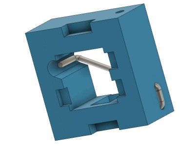
There is a github repository at https://github.com/phorton1/projects-ws2812bSwitchArray1 that contains all of the STL, Fusion 360, and C++ source files, as well as a complete description of how to print and assemble the switches and a discussion about how the program works and the full presentation of this project. Please visit there if you are at all interested. This Hackaday page is mostly for casual browsers ...
I also added a Thingiverse page at https://www.thingiverse.com/thing:3870539 for the switches themselves.
This is a followup to my previous page at Why doesn't someone make a ws2812 Switch Array?
THIS IS ONLY A PROOF OF CONCEPT DEMONSTRATION
There are a couple of major caveats:
- The technology shown here *may* suffice for DIY purposes, but is probably not mature enough, yet, for use in commercial products.
- This project is not for the faint-of-heart.
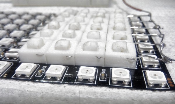
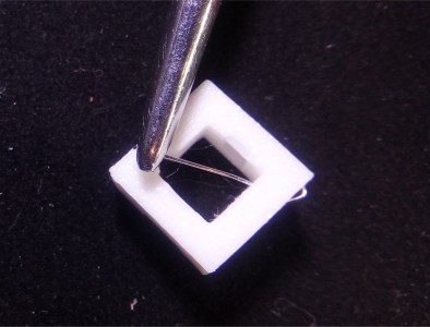
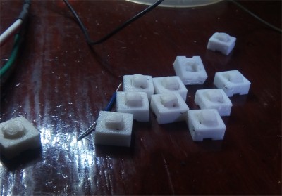
The switches can be difficult to print and assemble, requiring the use of a 0.25 or smaller nozzle, lowered print speeds, and good filaments. Getting the size, and bends, in the guitar string spring/contacts takes a lot of patience and at least a few tries.
HOW THEY WORK
The concept takes advantage of the fact that such LEDs arrays are fed with a single serial data stream that is successivly passed
down from the first LED in the array to each LED in turn.
Each LED "eats" 24 bits of color information before it begins passing the subsequent bits onto the next LED. We also take advantage of the fact that in the ws2812b protocol every bit, whether a "zero" or a "one" bit, consists of at least one "rising edge" delivered to each LED.
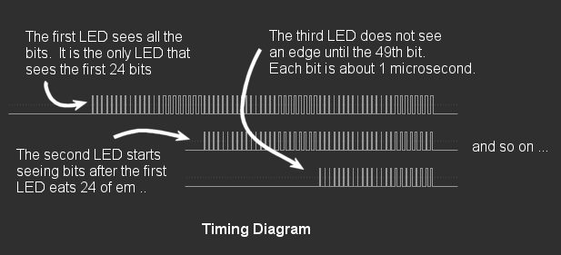
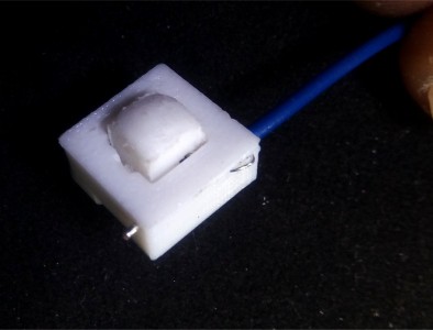
Thus, by attaching a switch to the DIN (data in) pin of each LED, and connecting all of those switches to a single common wire back to the
CPU, based on the timing, we can determine which switch, if any, is pressed during a refresh cycle.

The technique can only detect the FIRST button pressed in such an array. It cannot detect multiple simultaneous button presses.
This example works with an interrupt on the Teensy to measure the amount of time it takes, from the beginning of a refresh cycle until
the interrupt is triggered to determine which button is pressed. On the Teensy 3.2 at 90Mhz using the WS2812Serial library, it takes just
about 30 microseconds per LED. So, basically, we just divide the number of microseconds to the interrupt by 30 and we get the "button number" of the (first/earliest) button that is pressed.
This works well in this limited demonstration program, which makes use of the WS2812Serial, non-blocking, ws2812b library, which in turn uses DMA and a hardware UART to send the bits to the LEDs. Because it is non-blocking, and it leaves interrupts enabled, we can use such an approach.
THIS IDEA SHOULD WORK WITH ANY CPU and/or LIBRARY
Although this demonstration uses the WS2812Serial library and Teensy 3.2, this concept should be usable with ANY cpu that is currently used to control such a ws2812b, or other similar, addressable LED array, including Arduinos and Raspberry Pi's.
It should also work with different sized arrays, LED strips, circles, etc
For other ws2812b libraries, like the FastLEd or Adafruit NeoPixel libraries, that send the bits to the LEDS synchronously (one by
one via the CPU), an alternative approach can be used if interrupts are disabled, or if so desired for some other reason.
In that case the low level procedure that sends the bits to the LEDs just has to have access to a counter that tells it, at any time, which LED it is sending bits to (each LED takes 24 bits). It can then check the input line just after it sends out the rising edge of any, or all,
of the bits to each LED, and return the counter as the "number" of the button that is pressed.
Once again, please see my github repository for a...
 Petri Varsa
 johnowhitaker
 kmatch98