 Alexey Voronin
Principle of pulse induction
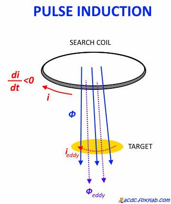
With a sharp decrease in the current in the search coil, its magnetic flux also decreases sharply. This phenomenon causes the occurrence of eddy currents in the target, penetrated by this magnetic flux. The resulting eddy currents counteract the reduction of the magnetic flux, which is manifested in a change in the voltage curve on the coil and is noticed by the device.
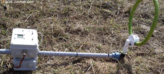
Assembled metal detector
Schematic

The appearance of the electronic unit (plastic box, version 1):
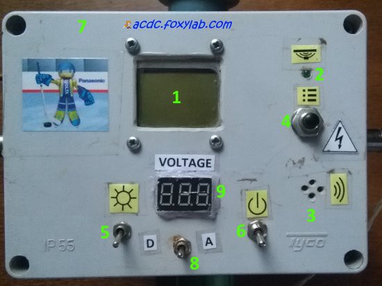
1 - LCD screen
2 - LED
3 - piezodynamic
4 - control button
5 - LCD backlight switch
6 - power switch
7 - signal strength indication LEDs
8 - voltmeter switch
9 - voltmeter display
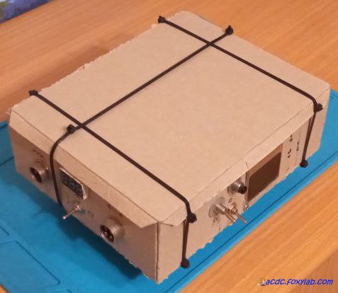
The appearance of the electronic unit (cardboard box, version 3):
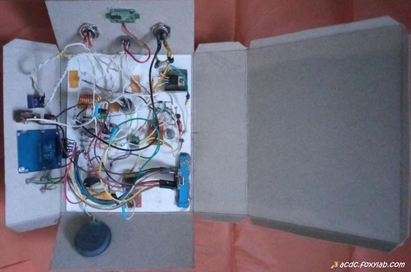
Interror of the electronic unit (cardboard box, version 2):

Interror of the electronic unit (cardboard box, version 3):
Working principle of metal detector
The signal from the search coil connected to the J2 connector, through the current-limiting resistor R2, is supplied to the diodes D1 and D2 connected in parallel, limiting the signal to ~ 1 V.
Such a weak signal for reliable detection needs to be amplified, for which I used the operational amplifier U1 LM358N, included in the traditional non-inverting amplifier circuit.
To process the signal from the search coil, I use the analog-to-digital converter built into the ATmega microcontroller.
To determine the presence of a target, the sum of a given number of sampled signal levels located at equal intervals from each other is calculated in a time window (evaluation window).
Then the integration of the sequence of obtained total values is performed (the integrator is emulated by software). The signal level at the output of the integrator is analyzed in the static mode of the metal detector.
When the metal detector is in dynamic mode, the integration results additionally pass through a high-pass filter, which is emulated by software.
At the filter output, a signal is obtained that characterizes the dynamics of the received signal.
When the output signal exceeds the threshold (the "zero" level set during balancing), the target is considered detected and an audiovisual indication is realized.
In the metal detector circuit, two "earths" isolated from each other:
analog - grounding icon
digital - case icon

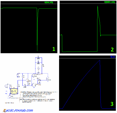
ASC file for simulation in LTspice XVII - in Files section.
You can play with the parameters and watch, for example, the voltage on the search coil (1), on the opamp input (2), the current in the coil (3):
Firmware
HEX and ELF files of current version - in Files section
Metal detector operation
The metal detector works in two modes:
- static mode (non-motion mode) (default) - the signal level is taken into account, does not require constant coil movement (can be used both for pinpointing the target location and the main search mode);
- dynamic mode (motion mode) - the dynamics of the signal changes is taken into account, during the search the coil must be moved above the ground surface
When a metal target object is detected, a sound signal of varying tonality sounds and LEDs light up. The signal changes in accordance with the dynamics (in dynamic mode) or the level (in static mode) of the received pulse.
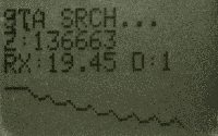
When the detector is turned on, auto-balancing is performed.
In the process of auto-balancing, the optimal initial delay and duration of the analyzed signal are estimated, and the dynamics of the signal (in dynamic mode) or signal level (in static mode) is evaluated. Also, balancing can be started/stopped during operation by pressing the control button. After the end of the auto-balancing, a short beep sounds and the “zero” value is displayed:

Using the button-controlled menu, you can configure the device parameters:

L - pulse duration (μs)
R - pulse repetition rate (pps)
I - integrator coefficient
F - filter coefficient
S - sound (on / off, ON / OFF)
C - display contrast value
Strong interference to the operation of the metal detector is caused by electronic devices operating in the vicinity!
LCD TV interference:
I will expand the description.
Detailed description (in russian):
https://acdc.foxylab.com/node/47
Some finds in garden with FoxyPI
Videos
Non-motion mode, "air" test
Motion mode, "air" and "underground" tests
Motion mode, "air" test
Non-motion mode, "air test with golden ring
To be continued...