 land-boards.com
In the last 3 logs we created an M6850 emulator based on the SIO that we already have. At the last step the program compiled correct. Let's try and get it to work. I'm sure I made mistakes when I did the previous changes. First I'm going to check the current build into GitHub with a note that it's a WIP.
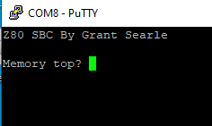
First, I've turned the Front Panel back on so that I can check the downloaded code. That is now as easy as changing the #undef to a #define for the Front Panel. Stepping through the first part of the code shows it loaded properly into the SRAM.
However, pressing RUN on the Front Panel doesn't show any output on the USB port. So much for just up and running. I am probably missing some subtle part of Grant's implementation. Just to rule out breaking something fundamental I switched back to the 9-build code and it ran fine. So it's apparently something related to the M6850 emulator.
Debugging I/O with the PSoC Debugger
Debugging is really nice with the PSoc. You can set breakpoints and run the code. The Z80 waits around for the PSoC and since it's a CMOS part there's no problem with asserting WAIT* indefinitely. Assuming the problem relates to the I/O code let's set a breakpoint at the beginning of the handler - function HandleZ80IO( ). The debugger stops at the beginning of main and has to be told to Resume Execution (F5 is the shortcut).
Since I have the Front Panel code still emulated I have time to restart PuTTY before hitting the RUN button on the Front Panel. This probably isn't strictly required since the PSoC waits for the USB to come up before it does I/O anyway.
F11 single steps through the PSoC code. The first transfer has ioCrtlRegVal with the value 0x1A. As you might expect that's a REGULAR_WRITE_CYCLE. The register ioZ80Addr shows that the Z80 is writing to address 0x80. Grant's INIT code shows this access first.
INIT:
               LD        HL,TEMPSTACK    ; Temp stack
               LD        SP,HL           ; Set up a temporary stack
               LD        HL,serBuf
               LD        (serInPtr),HL
               LD        (serRdPtr),HL
               XOR       A               ;0 to accumulator
               LD        (serBufUsed),A
               LD        A,RTS_LOW
               OUT       ($80),A         ; Initialise ACIA
Earlier we saw
RTS_LOW .EQU 096H
Stepping through the code shows it calling M6850WriteCtrl( ) as it should and the variable M6850_Ctrl is being set to 0x96 (as it also should). We can also see a TBD we left there which says there may be more to do when the control register is written. After stepping through this code i hit F5 to run until the next I/O request.
The next I/O transfer has ioCrtlRegVal with the value 0x1C which is a REGULAR_READ_CYCLE of the same location which should be a read of the status register. This could be where the problem is since that is uninitialized at startup unless there's code added to set the initial values. The SIO code didn't need any initialization of the values. The value is 0x00 and may or may not be initialized by the CPU. That would indicate that there is no receiver character but it also indicates that the transmitter is busy sending a character and it will never get set to anything else.
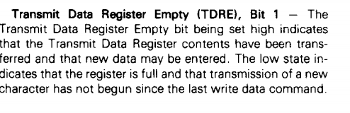
My guess is that Grant's software will spin on reading this until it gets set to indicate it is empty. Let's add code to initialize the M6850 status register before the code runs. We are missing any handler at all for this bit so it will also need to be fixed in the transmit routine. It looks as if this is the only bit that needs to be set since the other bits are all 0's when running.
We handle handshake in sending to the PC by holding off deasserting WAIT* until the PSoC code is called to send the data out the serial port.
We have to hit Stop Debugging to edit the program in PSOC Creator. The initialization code looks like:
///////////////////////////////////////////////////////////////////////////////
// void initM6850StatusRegister(void) - Set the initial value of the status reg

void initM6850StatusRegister(void)
{
    M6850_Status = 0x2;
}
We need to call this code before the loop in main( ). We also should put the function definition into the Z80_6850_Emul.h file to get rid of compiler errors. The code builds without error.
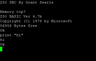
After downloading, we are rewarded with a very welcome sight.
Hitting enter in PuTTY doesn't work so we still have stuff to fix to get the Serial input to work but we're making great progress debugging in a relatively short time.
Let's set a breakpoint in the USB receive function in main( ). The function looks like:
        if (0u != USBUART_GetConfiguration())
        {
            /* Check for input data from host. */
            /* Only do the check if the buffer is already empty */
            if ((0u != USBUART_DataIsReady()) & (USB_To_Z80_RxBytes_count == 0))
            {
                /* Read received data and re-enable OUT endpoint. */
                USB_To_Z80_RxBytes_count = USBUART_GetAll(buffer);
                if ((USB_To_Z80_RxBytes_count == 1) & (checkSerialReceiverBusy() == 0))     // Input 1 character immediately
                {
                    sendCharToZ80(buffer[0]);
                    USB_To_Z80_RxBytes_count = 0;
                }
            }
        }
We set the breakpoint on the line with:
USB_To_Z80_RxBytes_count = USBUART_GetAll(buffer);
Pressing return in the PuTTy window caused the break to happen so we received data from the USB. The variable USB_To_Z80_RxBytes_count is 0 since we have not yet received any data (prior to this point). The variable USB_To_Z80_RxBytes_count shows that 1 byte was received as should also be expected. This matches the first condition of the line however the second condition is probably a problem.
if ((USB_To_Z80_RxBytes_count == 1) & (checkSerialReceiverBusy() == 0))If you remember in the earlier log I made a pure guess about how the RTS should work and I think I may have been wrong. Let's look at the function and single step through it.
///////////////////////////////////////////////////////////////////////////////
// uint8 checkSerialReceiverBusy(void) - Check the Serial port receiver status
// Returns:
//  0 if the port can take another character
//  1 if the port is busy and can't take another character

uint8 checkSerialReceiverBusy(void)
{
    if ((M6850_Ctrl & M6850_INT_RTS_MASK) != M6850_RTS_HI__INT_DIS)
    {
        return(1);
    }
    return (M6850_Status & SIO_CHAR_RDY);
}
Sure enough when we single step it shows the return(1) path being taken. So the PSoC isn't able to send data to the Z80. The problem looks like the not equal. The variable M6850_Ctrl is set to 0x96 and when ANDed with the mask 0x60 will be:
b'1001 0110
b'0110 000
=
b'0000 0000
Sure enough that looks like the problem but the fix is easy enough.
if ((M6850_Ctrl & M6850_INT_RTS_MASK) == M6850_RTS_HI__INT_DIS)Setting the debugger to breakpoint at the start of this function and single stepping shows the return(1) isn't happening, which is good.
The next line has:
return (M6850_Status & SIO_CHAR_RDY); The M6850 has a value of 0x02 in M6850_Status and 0x1 in SIO_CHAR_RDY. I should change the variable name of the second variable to M6850... Thes two ANDed together will return 0 which should indicate that the port is ready to receive characters. The main( ) function will now call:
sendCharToZ80(buffer[0]);
Looking at buffer[0] shows a 0x20 which makes me think I hit a space and not an enter. Let's keep stepping through the code to see what else is wrong. The function has:
void sendCharToZ80(uint8 rxChar)
{
    M6850_DataIn = rxChar;                                          // Put the char into the buffer
    M6850_Status |= SIO_CHAR_RDY;                                   // Rx Character Available
    if ((M6850_Ctrl & M6850_INT_RTS_MASK) != M6850_RTS_LOW__INT_EN) // Only set IRQ if it is enabled from the WR1 bits
        IO_Ctrl_Reg_Write(IO_Ctrl_Reg_Read() | 0x04);               // Set IRQ* line
}
Ah, now we are getting to the interrupt code. Let's see what the register values are before we go through this code.
- M6850_DataIn has 0x20 (the space I wrongly hit)
- SIO_CHAR_RDY is 0x01 - will set the receiver ready bit in the status register
- M6850_INT_RTS_MASK is 0x60 (it's a constant and doesn't change)
- M6850_Status is 0x20 which we initialized it to earlier. It should be 0x21 after we execute that line
The next line is executed to set the interrupt to the Z80 in the PSoC code as it should be. We'd need to be connected to the hardware with a scope or analyzer to see this happen, but we have seen this work with the SIO code. And the code returns as it should to main( ).
It's likely now that the problem is in the interrupt acknowledge cycle. Our guess that the vector should be 0xFF could be the problem. Let's set a breakpoint on the Interrupt ack code and see if the Z80 tries to do an interrupt acknowledge cycle. And sure enough that's the next breakpoint that is hit. That shows the next problem - which is hopefully the last problem since we are pretty far in the chain of events at this point.
Here's the code with the problem.
///////////////////////////////////////////////////////////////////////////////
// void M6850ReadIntReg(void) - Read the Interrupt vector

void M6850ReadIntReg(void)
{
    Z80_Data_In_Write(0xFF);
    IO_Ctrl_Reg_Write(IO_Ctrl_Reg_Read() & 0x7F);   // Clear IRQ* line
    ackIO();
}
The IO_Ctrl_Reg is inside the PSoC and has d1 as the interrupt line. However, I thought it was the interrupt status register in the M8650. It should be the same as the SIO code since it's part of the PSoC design not part of the M6850. The SIO has:
IO_Ctrl_Reg_Write(IO_Ctrl_Reg_Read() & 0xFB); // Clear IRQ* line
That did the trick! We are now rewarded with the keyboard working and BASIC running.
That was a bit of work to get 56KB of SRAM (instead of the 48K of the previous build) but it should be a good porting guide.
Discussions
Become a Hackaday.io Member
Create an account to leave a comment. Already have an account? Log In.