 land-boards.com
Probably one of the best references for the Z80 peripherals is um0081. um0081 describes the PIO starting on p 175. One of the more useful diagrams is the block diagram:
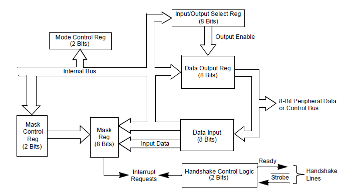
This shows the internal structure that the PIO has. Most importantly it shows the specific registers which need to be created as data values in the low level code contained in Z80_PIO_emul (.c and .h files). since they are all 8 bits values (or less in a couple of cases) they can be represented as uint8 types. These look like:
volatile uint8 PIO_Mask_Port_0;
volatile uint8 PIO_Vector_Address_Port_0;       // Mode 2 interrupt vector
volatile uint8 PIO_Interrupt_Vector_Port_0;
volatile uint8 PIO_Output_Register_Port_0;

volatile uint8 PIO_Mask_Port_1;
volatile uint8 PIO_Vector_Address_Port_1;
volatile uint8 PIO_Interrupt_Vector_Port_1;
volatile uint8 PIO_Output_Register_Port_1;
These values are defined as volatile since they could be changed by interrupt routines. They get placed into the .c file.
Digging further into the data sheet shows the bit fields of the registers and these are added to the .h file.
#define PIO_OP_MODE_0       0x00 // Output
#define PIO_OP_MODE_1       0x40 // Input
#define PIO_OP_MODE_2       0x80 // Bidirectional
#define PIO_OP_MODE_3       0xC0 // Control which bits are ins/outs
#define PIO_OP_DIR          0x01 // 1=input, 0-output

#define PIO_INT_EN_BIT      0x80 // 1=enable interrupts, 0-disable interrupts
#define PIO_AND_OR_BIT      0x40 // 1=AND, 0=OR
#define PIO_HIGH_LOW        0x20 // 1=monitor for high, 0=monitor for low
#define PIO_MASK_FOLLOWS    0x10 // Define mask bits follow
#define PIO_INT_CTL_WORD    0x07 // Signifies Interrupt Control Word
#define PIO_MASK_BITS       0xFF // Bit mask values

#define PIO_OP_MODE_MASK    0xC0 // Relevant bits
#define PIO_OP_MODES_WORD   0x0F // Relevant bits
We will probably tweek these values as we go along, but this is a good starting point. In the previous log we created the following function stubs which should be put into the .h file as function prototypes.
void PioReadDataA(void);
void PioWriteDataA(void);
void PioWriteCtrlA(void);
void PioReadDataB(void);
void PioWriteDataB(void);
void PioWriteCtrlB(void);
These also need to be added to the .c file and will be filled in as the functions are developed to handle each Z80 transfer. For now, just do something like this for each function:
void PioReadDataA(void)
{

}
The Z80_PIO_emul.h file should be added to the #includes at the top of the Z80_IO_Handle.c file so that it knows picks up the function prototypes.
#include <project.h>
#include "Z80_IO_Handle.h"
#include "Z80_SIO_emul.h"
#include "Z80_PIO_emul.h"
The include file gets added along with the other interfaces.
At this point the code compiles without error. Of course, we are missing the meat, but we have a solid skeleton for putting the meat onto.
In the next part we'll start looking at the details of the lowest level functions. What should happen when the Z80 reads the Status of Port A or writes the data of Port B?
Discussions
Become a Hackaday.io Member
Create an account to leave a comment. Already have an account? Log In.