Close
0%
0%

Bástya 2.0 (work in progress)

Our latest robot for telepresence and VR experiments.

Public Chat
Similar projects worth following
We want to build a robot platform prototype, what can be used to experiment with telepresence augmented with virtual reality headsets, and controllers.The goal of the project is to make an universal base. It can be upgraded with custom parts to solve specific problems. This is the next version of the robot.This version is heavily work in progress, and in early stage! The new main planned features of this version:- Adjustable "eye" level (human like height)- Robotic arms, remote controlled with the VR controllersPrevious versions:https://hackaday.io/project/26073-bstya-v15First prototype:https://hackaday.io/project/11956-robot-for-telepresence-and-vr-experiments

For the most detailed description please check out the project logs.

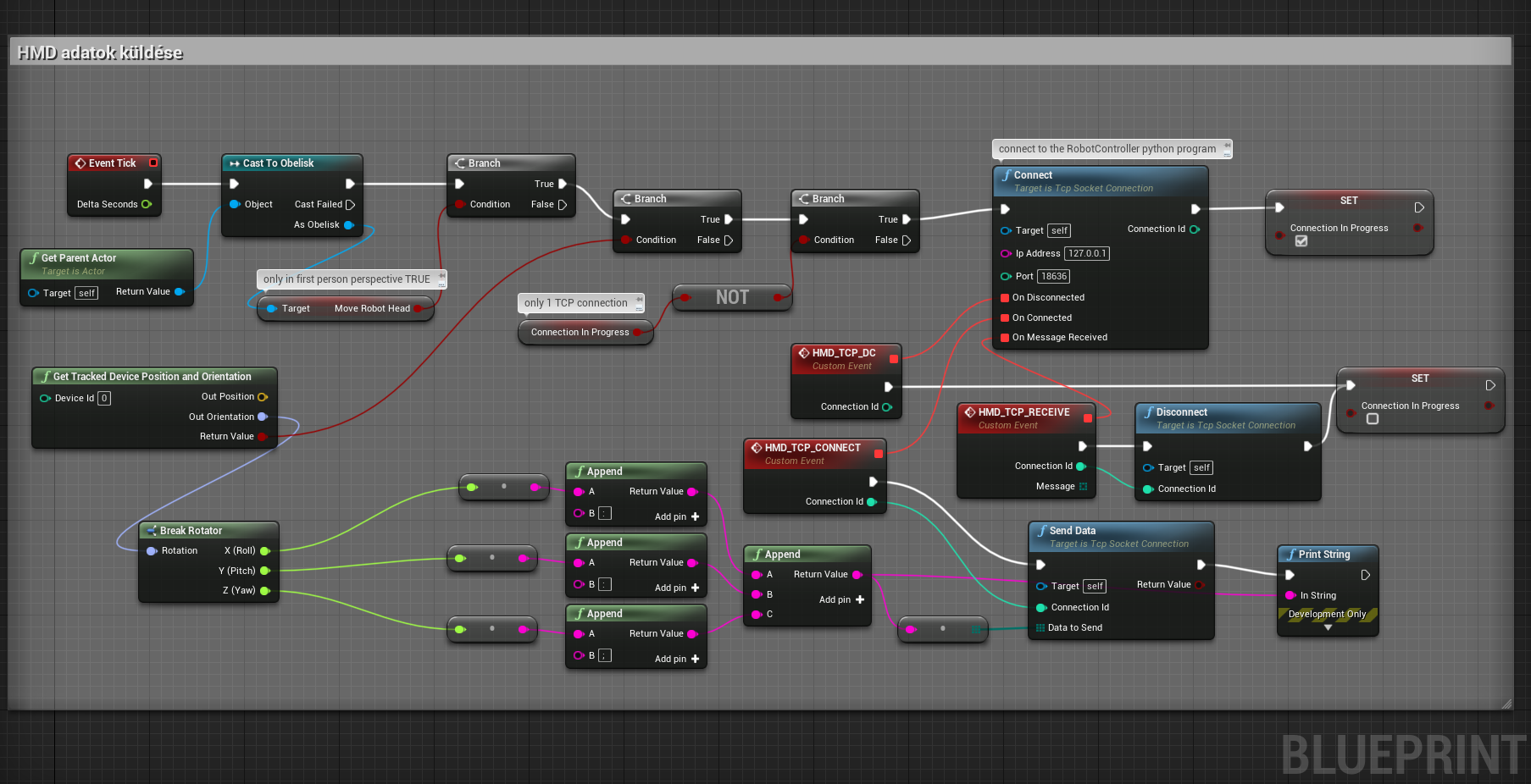
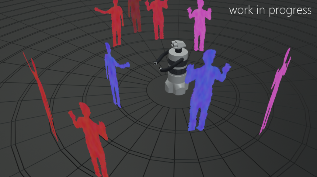
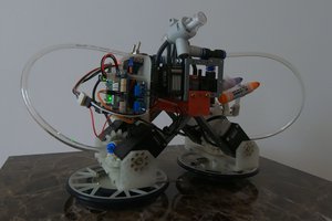
It is streaming video on wifi, and listen multiple sockets for head tracking control, and movement control.

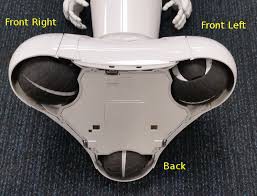
Currently we are using HTC Vive for the development, but it can be operated with similar PC connected HMDs.

Besides that, you can connect to the robot with HTML5 compatible browser and watch the video stream. Because of the HTML5 we can send the mobil device orientation back to the robot, so it can adjust the camera position in real time. You can control the robot movement with joystick connected to PC, or tablet.

If you don't know something what we did, why we did that way, feel free to ask, and I will try to answer it.

We are glad if you make suggestions, or tell your ideas to improve our robot.

View all 22 components

  • Opencv AI Competition 2021 #oak2021

    BTom08/09/2021 at 22:40 0 comments

    We are finished with the final submissions ! 

    We made a short movie about the Obelisk robot, because we thought it will be more entertaining to more people. In this year, and the previous one, we couldn't present the robot at exhibitions, or events. We shoot the video not exactly about the robot but with the robot :)

    In the movie we obviously deviated from reality in some scenes, but the things you see in it, is based on real solutions what we built into the Obelisk robot, or something similar what can be done with the OAK-D cameras. 

    //What we built into the robot can be found here in the logs, and in the final report what we made for the contest submission. (and the git repo)

    The other important decision in the team was to share our Obelisk robot git repo, for the competition and for everyone who interested in some way about our project. You can find the repo here: https://github.com/Essort/fantastic-robot (by the way, GitHub suggested the repo name, how we can say no to this :) )


    In the repo you can find:
    - the whole unreal engine project, with some demo maps, where we test, and try out new features with the Obelisk

    - separate python program for the OAK-D cameras and features

    - OAK-D camera mount for the Bosch profil ( STL, OBJ )

    - setup descriptions for the raspberries on the robot

    In the future we will try to keep expanding this open repository with new solutions.

  • Lots of progress in the past month

    BTom07/31/2021 at 12:54 0 comments

    I try to catch up with the progress report. First the most impressive thing, finally the robot has glowing eyes (because everyone knows that robots have glowing eyes :) ). 


    Jokes aside, we are finished with the installations of every cameras, and Raspberry Pi computers. The network is working too. There was some under voltage problem in the Pi, but we built in a powered USB hub for the OAK-D cameras, and it solved it.

    Currently we have some separate program for the head, and chassis movement for easier testing.

    With the depth map I'm trying to make it work smoothly with Niagara particle system, and only using the blueprints.

    The object recognition working, there is a separate map for testing it in VR.

    We found some problems while testing the robot:

    - the suspensions in the current version are practically not existing. If the robot is on a flat ground it's works perfectly. But when we drive it on a bumpy surface the whole robot sakes. We are planning to redesign the suspension with tension springs.
    - the main circuit board have some contact problem, probably caused by the shaking of the robot.
    - we have to replace the small touch screen too at the back of the robot.

    We are working on a presentation video about the robot, and some of the possible features. Not every feature is built in yet, but you will see it in the video probably at the next weekend. Currently there are no exhibitions where we can bring the robot, so we thought an interesting video will be more entreating for a bigger audience than a technical presentation about the features.

  • Dual stream setup (how to)

    BTom06/11/2021 at 08:29 0 comments

    Setup of the RPI:

    Create SD card with Raspbian lite image, and in the terminal run the following. In the previous robot we used the mjpeg-streamer This time we are using the ustreamer

    sudo apt-get update
    sudo apt-get upgrade
    sudo apt-get install git
    git clone --depth=1 https://github.com/pikvm/ustreamer
    

     or you can use the same version we installed on the robot: https://github.com/Essort/ustreamer

    cd ustreamer/
    sudo apt install libevent-dev libjpeg8-dev libbsd-dev libraspberrypi-d
    make WITH_OMX=1

     
    checking the cameras

    v4l2-ctl --list-devices
    v4l2-ctl -d /dev/video0 --list-formats-ext
    v4l2-ctl -d /dev/video2 --list-formats-ext

    If you can't see the compatible formats, check lsusb, and dmesg for troubleshooting.  In our setup, one webcam got two /dev/video, so this is why we use video0, and video2. You should check your result of the v4l2-ctl --list-devices to set up your scripts according to that.


    You can start the stream with this example commands

    You have to modify the following command with the previous command results, if your camera doesn't support the format, and resolution. You have to change the --host to the device IP

    ./ustreamer --device=/dev/video0 --format=MJPEG --host=192.168.0.16 -p 8080 -r 1280x720
    ./ustreamer --device=/dev/video2 --format=MJPEG --host=192.168.0.16 -p 8081 -r 1280x720


    setup the cameras to auto start when raspberry booted

    sudo apt-get install screen
    

    We made 2 start scripts:  "startLeftCamScreen" and one for the other camera: "startRightCamScreen"

    # startLeftCamScreen

    cd ~/ustreamer && ./ustreamer --device=/dev/video0 --format=MJPEG --host=192.168.0.16 -p 8080 -r 1280x720 --allow-origin *

    # startRightCamScreen

    cd ~/ustreamer && ./ustreamer --device=/dev/video1 --format=MJPEG --host=192.168.0.16 -p 8081 -r 1280x720 --allow-origin *
    

    Set them to executable

    chmod +x ~/startLeftCamScreen
    chmod +x ~/startRightCamScreen

    Edit the root startup script fil

    sudo nano /etc/rc.local

    And the following line before `exit  0:

    # Run a command as `pi` from the home folder 
    # in a screen named `pistartup`
    su - pi -c "screen -dm -S leftCam ~/startLeftCamScreen"
    su - pi -c "screen -dm -S rightCam ~/startRightCamScreen"
    

    After this if your reboot the RPi, the stream will automatically start.


    There are som helpful commands:``

    #check for running screens
    screen -list
    
    #ressume screen
    screen -r
    

    At VR (PC) side, you have to make a simple html for embed mjpeg stream because currently webBrowser in the UnrealEngine widget can't open the stream directly. With the simple HTML you can configure the position screen size etc. with the html for the VR display.

    <!DOCTYPE html>
    <html>
    <head>
        <meta charset="UTF-8">
        
        <meta name="mobile-web-app-capable" content="yes">
        <meta name="apple-mobile-web-app-capable" content="yes">    
    
        <title>Right</title>
    </head>
    
    <body style='background-color:black; width:1280px; height:720px;overflow: hidden;'>
    <div  style='display:flex; width:1280px; height:720px;'>
        <div style='position:relative; left:0px;'>
            <img style='width:1280px; height:720px;' src="http://192.168.0.16:8081/stream" />
        </div>
    </div>
    </body>
    
    </html> 


    In the unreal engine we use the same trick what we used in the previous version, with a little update in the "stereo camera" material.

    The concept is the same we are using SceneCaptureComponents and a widget with browser. The A showing the left camera stream in the widget web browser, and B is the right.

    C is the first person perspective camera. Front of it is a simple plane with the camera material.

    This is the "stereo camera" material:

    There is a "custom" node on the picture with this code: 

    return ResolvedView.StereoPassIndex;


    //We tried to setup this with media stream, but we can't make the NDI stream output from the webcam at the robot side.
    Other thing we will try out is the WebRTC instead of the HTTP MJPEG stream.

  • Progress with the software side

    BTom05/25/2021 at 08:50 0 comments

    We are finished with the motor controller Arduino code, there are still some things to do for the touch screen control, and reading the telemetry from the robot. Now we can drive the robot wheels with the joystick like in the "Bástya 1.5" robot. Meanwhile the changes of the wiring in the robot is completed too. There is no more contact error in the motor controller.

    The new program for this head mechanic is completed.

     This is the working solution to the VR HMD position reading from the unreal engine. We can send the data to the robot with TCP connection. The blueprint is made with this plugin:  https://unrealengine.com/marketplace/en-US/product/tcp-socket-plugin 


    In the unreal engine there is a working first person perspective, and third person perspective view change function.

    There is a boolean variable at the end what we can switch with the perspective change. We only move the robot head in sync with the user head if it's in the first person perspective.

    In VR with first person perspective you can view what the robot head sees in stereoscopic view. Or you can switch to third person perspective and look around the robot. In the third person view we are working on displaying the data from the OAK-D devices. 

    The first detection type will be object recognition with distance. We will divide the space in VR around the robot like in the picture: 

    The numbers represent the sides of the robot. 1 - front, 2- right, 3 - back, 4 left. The A,B,C fields are the distance from the robot. We will put the detected object in the appropriate field. If the object is in the green A, it is the safe distance we will show it on the third person view in VR.
    If the object is in B, it's require more attention, so we will limit the robot speed to that direction. If the object is in the C red field, it's dangerously close, we will inhibit the robot to move to that direction. (It's similar than car parking radar)

    We are working on to visualize the raw depth data of the OAK-D cameras, with the unreal engine built in "Niagara visual effects system". It will only serves as visual feedback in VR for the controlling person to be able to get to know the surroundings better.

  • Progress in the past weeks

    BTom05/02/2021 at 00:09 0 comments

    We finished with the chassis for now, and made belt tensioning.

    The electronic installation is completed with voltage regulator, mikrotik router, programable touch screen, arduino mega with our custom shield. The cable connections to the motors looks fine at first, but at testing we found out most of the cabels are too fragile, so next week we will replace them.

    We are using the Mikrotik hap ac2 routers https://mikrotik.com/product/hap_ac2 One on the robot, and one at the remote control PC. These are bridged with nv2 protocol.

    Today we placed the head on top of the robot, and it looks like we will have to make some resonance dampening, but it will works.

    At programming side we finished with the first version of the arduino mega code, and the python programs for remote controlling (robot and PC side) . We made progress with the new head controlling algorithm we will post details .

  • New parts arrived, and the head mechanics nearly completed

    BTom04/17/2021 at 12:46 0 comments

    In the past weeks we wait for parts to arrive, and we rearranged the workshop because in the past year we rarely used it.

    Only the PWM shield not arrived yet. That's will be needed for the head mechanics.

    Camera for the stereoscopic view

    Meanwhile, the plans for the new head mechanics completed, and the first version is 3D printed. The previous version is working too but we want to upgrade it to be more stable, and less demanding for maintenance. The is based on the adafruit animatronic robot head, we modified it a bit, for our requirements. https://learn.adafruit.com/3d-printed-animatronic-robot-head/design

    base of the head mechanics
    head mechanics
    head mechanics parts

    The programming is progressed too, but nothing spectacular. Currently we can send data from the OAK-D to the unreal engine.

    The next step is to display the data in the unreal engine. The data package currently contains camera ID (so we know which camera is sending the data. Its defined in a config file which camera is placed what side of the robot.) and the recognized object, and it's coordinates with distance (x,y,z)

    We are currently discussing the remote control of the robot in the team. The are 2 competing solutions:

    The joystick connected to the unreal engineThe joystick connected to the EssortRobotController
    pro:
    - in the future we want to test other control solutions than the joystick
    for example walking in VR will be simpler if the remote control already
    implemented at the unreal engine side
    - we can simulate the movement in a virtual space without the robot
    it will be much easier to test the out the solution
    - we can use the unreal engine collision model to stop the robot

    cons:
    - the robot is only usable with unreal engine 
    (we can't remote control without it)
    - generally not a good idea to implement collision avoidance
    at high level
    - it will add some overhead time to control the robot.
    probably negligible
    - we have to use RawInput plugin to our joystick
    probably not really hard, but we didn't have experience with it
    pro: 
    - we can implement faster the previous version
    of the controller to this python program
    - this program handle the obstacle detection data, probably
    this is the best place to implement collision avoidance 
    - we can remote control the robot without unreal engine
    with the collision detection

    cons:
    -  if we want to test out new remote control solutions,
    we have to program it from scratch with python
    - currently it's a separate program, we have to
    implement it in the EssortRobotController
    - it's harder to simulate, and test out the program
    - probably for the walking in VR remote control we have to
    implement the unreal engine remote controller anyway
    because the VR controller data is already available at the
    unreal engine side 

    At now it looks like we will implement both solution in the future, but first we will probably implement the EssortRobotController one. We will decide it in the upcoming weeks.

  • Documenting the working principle

    BTom03/28/2021 at 15:54 0 comments

    The TCP socket connection working between the current version of the unreal engine and the new robot control program. Thanks to this plugin: https://github.com/CodeSpartan/UE4TcpSocketPlugin

    At software side we are experimenting the new TPS view concept, and implementing the Bástya 1.5 features to this version of the robot.


    We made two explanatory illustrations about the communication protocol, head, and robot movement. 

    Communication from PC to the robot
    Robot movement direction

  • New parts and current tasks

    BTom03/21/2021 at 10:26 2 comments

    We updated our part list with the additional components, refreshed the B6 profile part numbers.

    Currently we are working on the extension of the chassis. We build two more level on the robot. 

    The first one in the future will contains the lift mechanic. It will rise the eye height of the robot. But this isn't needed for the opencv competition so we will return to it later.

    The second stage is where we put the electronics, and the OAK-D cameras. We will put the robot head on top of this satage. The new head will be in another project log. Approximately the top of the robot 1 meter above ground.

    In previous weeks we received  the OAK-D cameras, Mikrotik routers, and the RPI boards. 

    OAK-D cameras

    The robot controller board is ready to be installed too. There will be more information about it later.

    Essort robot contoller board

    At last but not the least this is the first version of the data flow schematic of the robot. 

    Bástya 2 - "Obelisk" data flow schematic

  • #OAK2021 - Phase 2

    BTom03/06/2021 at 13:39 0 comments

    We was chosen as a Phase 1 Winner in OpenCV AI Kit 2021!  All the winners are listed on the official competition page at https://opencv.org/opencv-ai-competition-2021/#phase1-winners-list

    Our plan is to put OAK-D cameras on the robot to implement obstacle detection and pose estimation. When users remote control the platform, currently they see first person view and they are not aware if there are other people or objects around them.

    With the pose estimation waving can be recognized thus the robot can automatically turn towards them and start automagically interacting with them.


    We will display the additional data in VR. The remote controlling user will be able to switch between FPS, and TPS view.

    In the following 3 months we will be documenting the process here.

  • The new wheels (why we bought it, and didn't build it)

    BTom10/20/2019 at 10:16 0 comments

    In this robot, we need a wheel with much higher carrying capacity than the previous wheels we used.
    In the Bastya 1 we used WEX omni wheel: 4" Omni-Directional ( https://www.vexrobotics.com/edr-wheels.html )

    The first ide was that, we will build omniballs for the wheels: ( https://www.youtube.com/watch?v=ZOCdI2gzMqI )  It looks like simple and much higher carrying capacity.

    We used this for reference:

    The first version:

    It consist hamster ball and laser cut plastic sheets. We can't find the required sized ball. (in this picture, the wheel bearing placement isn't completed )

    The next versions is fully 3D printed:

    It came out it isn't have enough carrying capacity (probably it can be fixed with more thicker walls). On the other side of the hemisphere we need too put something to rotate. In the small models its a small ball. (our first plan was that if we disassemble some old PC mouse we can use the ball, and the mechanic parts to hold in place. When we examine the size of the 3D printed hemisphere, and the size of the robot, we thought it will be too weak.

    After that we found out another version of the omni ball used in the Pepper robot.

    So with this reference we started to design our version of it:

    When we calculated the price of this version, and the necessary machining of the parts, we thought it will be better if we stick with the omni wheel what we used previously in lots of robots:

    The next idea was we will build the omni wheel:

    We thought we can build an omni wheel easily, but after lots of experiments, it looks like it isn't a trivial task. In small scale we already built omni wheels with 3D printed. The bigger wheel we designed for this robot consists of aluminium and rubber wheels. The aluminium part easily can be made with CNC machine. And the rubber wheels contains a 3D printed reinforced core. We thought it is a solid plan, and thought with some experiments we can make high carrying capacity wheels cheaply with the 3D printed rubber rollers. 

    (spoiler alert: it came out it's much more expensive in the end, without counting the time we put in it. But we learnt a lot from it)

    So in details:

    First we designed the wheel, and the rollers:

    We looked around about the heavy duty omni wheels and it looks like with bigger roller is the better. So we went that way with the planning.

    After that we designed the core of the rollers. First idea was that, if we can mold it with 2 component rubber, we can adjust the flexibility, and hardness. The reinforced core contains the axle, and with the 3D printed core, we thought it will not cut the rubber when we put weight on it.

    These is the variations for the roller core:

    The first one, is designed with the concept of weight distribution with a grid: (it was fun to learn how to make shape like this in the CAD program :) )

    It came out of the printer so dense we can't mold it.

    The second version contains less columns and with new grid distribution: (8, 6, 4 columns with 2 directions)

    This version is possible to use in the mold, but when it came out of the printer it was too brittle.

    The next version contains more rigid 3D printed object.

    With this version we made some test molds. We designed a reusable mold. The core is fixed in the center with an axle.

    It came out looking good, but when we put weight on it. It crushed the 3D printed core.

    Another problem we found out in the first tests we can't variate the flexibility easily. We thought we need a vacuum chamber for this.

    The next idea was that if we can make the rolleres with lathe from some material it will be better, and cheaper. We found out that the plastic what is used in these rollers are not cheap (and didn't have lathe, so we have to order the rollers) 

    After this we made some calculations and looked like it is cheaper to buy the wheels :)

    Finally we ordered the wheels:...

    Read more »

View all 11 project logs

Enjoy this project?

Share

Discussions

Similar Projects

Does this project spark your interest?

Become a member to follow this project and never miss any updates