Close
0%
0%

Quad UART for RC2014

Fitting a QUART into a pint pot

Similar projects worth following
A board to add four serial ports to an RC2014 system using the XR82C684

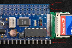
The RC2014 system traditionally uses a 68B50 or a Z80 SIO which in turn means you are stuck at a fixed baudrate on two ports or also need a separate CTC to do baud rate setting. I wanted a few more ports and configurable board rates without taking up lots of slots.


The board itself uses the XR82C684 which is a quad UART along with two timers and some IO pins (not many in this case as the 44pin part omits most of them). The logic isn't that tricky. A 74HCT688 matches A7-A1 of the address and M1 high, IORQ low. A 74HCT32 generates the needed read/write/iack signals and the spare gate is used to check that A0 is low.


The upper addresses are used to drive the address bits on the UART so that we don't waste precious I/O address space on the Z80, and that's about it other than a single 74HCT00 gate to invert the reset line to feed to the UART.

The board uses the standard RC2014 clock. If you are running at a weird non RC2014 standard clock you will get weird baud rates and need to use the counter mode (and so lose the timers). The QUART IC itself is limited to 8MHz so if you are running at custom high speeds (eg Z180) you'd need to update the design with a clock divider or own crystal.

quart.zip

Gerbers

Zip Archive - 103.09 kB - 04/01/2020 at 21:50

Download

uart4.kicad_pcb

Kicad 5

x-kicad-pcb - 441.83 kB - 09/21/2019 at 12:55

Download

uart4.sch

Kicad 5

x-kicad-schematic - 22.73 kB - 09/21/2019 at 12:55

Download

  • Fuzix Drivers Completed

    EtchedPixels11/10/2019 at 01:05 0 comments

    It took a while to bash it all into shape but Fuzix now has the needed code to use all four ports of the QUART. Not sure I actually needed four but it was fun to design. Maybe 8 next...

  • Initial Upload

    EtchedPixels09/21/2019 at 12:56 0 comments

    At this point I've got the board talking to my test code and it seems to be working. I've yet to fully test out the interrupt logic, all four ports and all the rts/cts lines.

View all 2 project logs

  • 1
    Basic Construction

    Before you build it note that you need an open frame PLCC socket or you need to put C3 on the back of the board (bent to lie flat). Either way you want to solder C3 before you fit the PLCC socket.

    It's easier to get the angled headers down first before soldering resistor packs and the chip sockets. The jumpers and PLCC socket are the highest.

    For normal use cases jumper JP1  1-2 so that IEI is pulled high and J2 1-2 to put the card at 0x7E. (That's the pin pair nearest the RC2014 connector). The jumpers control which address lines other than A0 must be low (A0 must always be low). Unfitted is high.

    JP3 and JP4 connect port 1 to the RC2014 backplane RX/TX for use with things like the PI terminal or the forthcoming Gluino card.

    If you are using Z80 IM2 then jumper JP2 and set JP1 2-3 so that IEI/IEO are in the expected chain.

View all instructions

Enjoy this project?

Share

Discussions

Dan Maloney wrote 09/26/2019 at 15:14 point

Pretty cool. Did you catch our Hack Chat with Spencer back in May?

https://hackaday.io/event/165304-retrocomputing-for-the-masses-hack-chat

  Are you sure? yes | no

EtchedPixels wrote 09/26/2019 at 23:56 point

I did yes, I think there's a picture of my 12 slot RC2014 beast in the chat somewhere.

  Are you sure? yes | no

Similar Projects

Does this project spark your interest?

Become a member to follow this project and never miss any updates