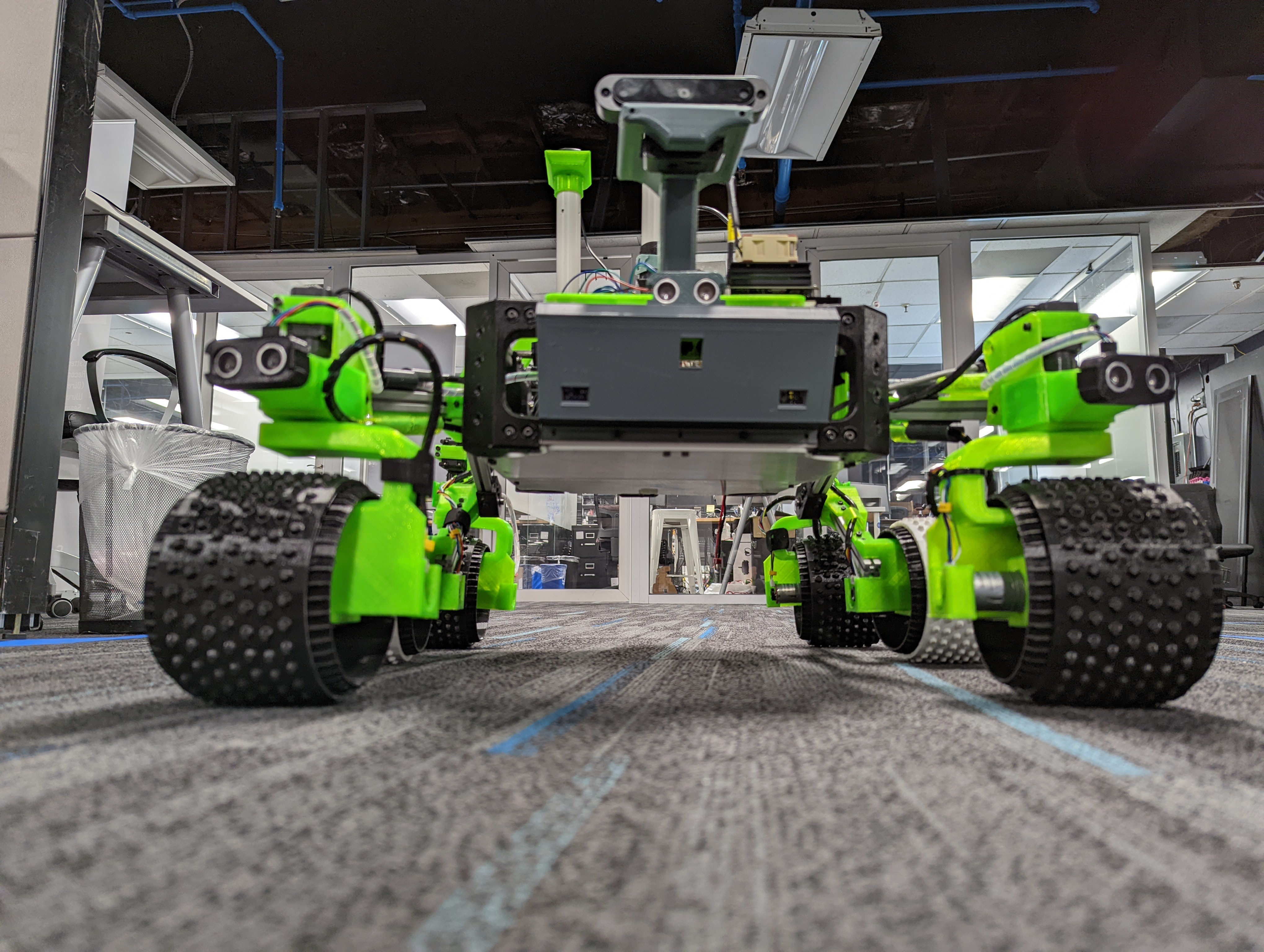
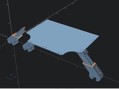
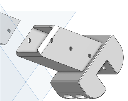
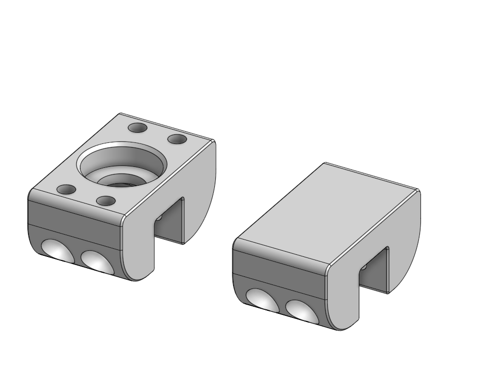
• Networking Gear Splurge...

    Steve02/13/2022 at 11:55 0 comments

    I've been eyeing the botblox.io networking products for months but avoiding clicking on "Buy" because they were pricey but also came with a hefty shipping costs from the UK that made the on-my-desk costs almost 2X what the devices themselves costs. Which, I get and which is the world we live in now. So I've been looking and waiting and dreaming and waiting and continuing to struggle w/ USB and udev .

    The good news is that there's a cheaper shipping option now and flush with a little extra Xmas cash, I did mash the "Checkout" button and this showed up on my desk at CircuitLaunch within a few days of ordering it last month.
    .


    In case it hasn't sunk it yet, it's a tiny,tiny little gigabit network switch designed specifically for robots and drones. I'll let you go get all the specs off the Botblox site, but just look at it sitting on top of the TP-Link 5-port 100Mbit switch it's replacing. So tiny! So glowy! Botblox have been able to shrink a switch down to this size by engineering out most of the transformer/power management electronics that are in a typical switch. As a result, it's really meant to be installed in an isolated environment, like, say, a robot that needs its own internal LAN that doesn't really connect to the outside world.

    So far it streams RGB & depth data off the OAK-D camera at 30FPS just fine and brings the entire networking stack up to 1 Gbit everywhere AND a 1A power savings. The electronics/compute bus is down to 2-2.5A draw now and that's low enough to dump the current honking 10A step-down that I got as a hand-me-down when I was first putting Tenacity together 3 years ago. 

    Slowly, bit-by-bit, early parts are getting swapped out for smaller, lighter, more capable, less power-hungry ones. The L298N motor controllers are gone, replaced with a VNH5019 from another robot a few months back. The tangle of Arduino Nanos, USB cables and udev rules are being replaced with Ethernet-capable Teensy boards( One of which, TBH, probably could run the entire rover, minus the cameras, if I felt like rewriting the entire control stack in custom C vs ROS) .

    The new shininess, tucked away under the top deck. It needs a proper 3D-printed case, but this will have to do for now.

  • Getting more operational

    Steve02/13/2022 at 03:09 0 comments

    The tempo on major build work on Tenacity has definitely slowed over the past few months. At 2.5 years in, there's not a whole lot of major structural improvement to be done. I've been working on it steadily, but these are enhancements and improvements to things that have been bugging me over the long term. 

    Let's start with enclosures for the front and back ends. I created these over the holidays in December/January. 

    One thing that has been really useful is the addition of some "Debug Ports", so I don't have to go scrabbling around inside the main box to plug into the LAN or flash new code onto the Arduino, etc.
    Shown here: Ethernet, USB and HDMI.

    I also designed in some holes for the toggles on the main power switches. They're recessed underneath now along w/ their wiring. The green "roll cage" like bar in the background there is actually a carrying handle for when I need to haul it around.

    The front here has slots for the cliff sensors, a pair of VL53L0Xs and slot for another camera or other sensor. Again, out with the sticky tape and zip-ties for actual sockets to mount things on :)


    The real remaining work to be done at this point is software and I've been getting some work done on that too with the OAK-D depth-camera.

  • "Assisted Teleop"

    Steve07/02/2021 at 18:05 0 comments

    I've been lucky enough to be able to spend some time with the Boston Dynamics "Spot" quadruped robot and one thing I noticed right away was that it does obstacle avoidance even in teleop mode. On many robot platforms, "teleop mode" is a kind of dumb joystick control where the motors are being driven directly by joystick input. If the driver isn't paying attention or doesn't have sufficient skill, it's entirely possible to drive it into a wall or off the top of the stairs.  Not "Spot". It deftly weaves and jogs around posts and ducts in the middle of the room, stops in front of doors and halts at the edge of stairs.

    This seemed like pretty low-hanging fruit to add to Tenacity, so I made a weekend project out of making some sensor mounts, installing them and writing up some code for an Arduino to talk to them and publish the data as a ROS Range message. There are two HC-SR04 sonars, left and right, on the front wheel pods and a V53L0X in the center for a "cliff sensor".  

    I CAD-ed up a mount to fit on the brackets of the steering columns. They conform to the part and clip into the holes on either side. The part is mirrored for a left and right mount. I wanted something I could mount sonars or even a small camera like an ESP32-CAM to, so I left the attachment space purposefully flat and blank with the idea that they'd get mounted via double-sided tape or velcro.


    A Python script subscribes to the ROS /ultrasonic topic(s)  and publishes turn decisions to /cmd_vel to do the obstacle avoidance logic. 
    Here's a demo. I'm driving the rover forward here, deliberately aiming it at walls, shelves and other random obstacles. It's really doing quite well I think. I don't think I could cut some of these turns quite this close even if I tried. I'd love to hear your thoughts and comments.

  • Full-Metal Roving

    Steve05/15/2021 at 03:28 0 comments

    I got these in the mail the other day:

    Sawppy builders will recognize these as the triangular wheel hubs used to mount the wheels to the drive shafts of the motor pods. My buddy Ed "Steamboat" Haas and I have been collaborating on replacing the 3D-printed parts of the motor pods that have failed most often with metal equivalents.  We're about a 2-hour drive from each other and the pandemic hasn't made collaboration any easier, but we've both got 3D-printers and tools and Internet connectivity and the hacker mindset to do crazy things and this the result. A bunch of hand-machined, hand-tapped triangular wheel hubs that started life as a single piece of round Aluminum stock.

    I had to do a bit of filing and Dremel-ing to get them to fit inside the wheels, but that didn't take long. The Aluminum is soft, almost butter-like in comparison to the steel axles.  

    I also had to grind out the detents on the axles a bit deeper and make them lie a bit flatter because the metal hubs don't flex and deform at all, so any angles or nubs in the detents showed up in the new hubs tilting against the shaft which led to the wheels themselves visibly processing when driven.

    For somebody like me who knows just enough about materials to be dangerous, this was a bit of an eye-opener. I knew there were divots and digs in the shaft detents, even if they appeared mostly flat, but the way the PETG conformed to these, even under the tension of the set screw biting into the shafts really masked these imperfections quite a bit.  Even after this additional filing, the wheels still process a bit when free-wheeling, but this is mostly damped out with the rover on the ground and the wheels come under weight. On a couple initial test drives, this doesn't seem to affect the way the rover drives. I kind of don't care for now because this rover is still such an experiment and the metal hubs should go quite a ways to solving my problems of having to do wheel maintenance and swap out PETG hubs after a day's worth of driving.

    Ed has his own album up over on Flickr documenting how these were made.
    He also has a lot of neat stuff over on his Thingiverse account

  • Nobbly bits

    Steve08/24/2020 at 18:05 7 comments

    I've been playing with this idea of an "airless" tire for Tenacity for a while now. I like Roger's original design WRT faithfulness to the actual style and dimensions of  the Perseverance Rover wheels, but I think they're going to wear pretty quickly in the off-road conditions I hope to have Tenacity rolling around in.

    I like the design of the wheel "knuckles",  and don't want to completely redo all that, so as an intermediate step I was thinking last  weekend about "Hey, maybe I could give it some slip-on treads...".
    So, here you go: Procedural, parameterized slip-on "snow-tires" for your rover !
    OpenSCAD script here:

    https://www.thingiverse.com/thing:4582109

    Pics below...

  • Now we're crawling!

    Steve08/10/2020 at 05:09 3 comments


    I just really could not be happier at this point and have been posting this everywhere else on the Intercats, so this page should get the update too :)

    The new metal bits I described in the previous post are installed. Set screws are biting hard against metal vs. sqooshing into nylon. It's like a whole new rover!

  • Shiny things and milestones

    Steve08/05/2020 at 01:55 0 comments

    I've decided to plant a flag on some of the 3D-printed aspects of Tenacity, makes notes to myself(and here) and move on. I've got lots left to do and can't really do it when axles snap every 10-30 minutes. I've been working on Tenacity for a bit over a year now and have been through a bunch of iterations of the drive, steering and suspension components and am ready to move on. 

    So, the question is:
    Can you, in 2020, 3D-print yourself a robot that weighs almost 20 lbs and have it support its own weight and move around ? 

    I'm going to answer that with a qualified "Yes". First, you're not going to do it  just with PLA, or even just with PETG. You will need Nylon or some sort of Nylon-like blend for load-bearing parts and even then you're going to be replacing long, thin parts pretty often. But Tenacity did take its first rolls on all 3D-printed parts, except for the 1515 Aluminum body frame, center suspension rod and various nuts and bolts. I was able to set it down on the ground and the rocker-bogie shafts and the axles on the wheels and the corner steering all bore the weight of the rover.

    So, where I'm going from here is moving back over to metal for the long, thin parts like the axles and shafts(about which in the next post) because as much as I've enjoyed being a total materials geek, I really need to get to where I can have Tenacity reliably rolling around and start testing some software, get the ROS stack firmed up, etc.   I'm excited that I got as far as I did, and certainly just having the printed parts get me this far has really helped bring my version of SAWPPY to life.


    MaterialPartResultLongevity           
    Notes
    ABS Steering & Drive shafts
    Snapped off clean.       
    A few hours
    These snapped  when going over a hard bump.
    Sometimes along the retainer ring slot, but more often where the part was held by a set-screw.
    Carbon Fiber-Nylon blend(NylonX)
    Rocker & Bogie shafts, steering shafts,
    Deflected, but held up the weight of the whole rover. Broke under shocks/stress.
    Static:Indefinite
    Rolling/Operational: 10-30 minutes
    These snapped at the retainer-ring slots as the rover entered a turn at speed and the weight/stress shifted to one side.
    Nylon, even with carbon-fiber stiffening, really wants to be part of an object with some "bulk" and not a long, thin part.
    Carbon Fiber-Nylon blend(NylonX)                                                                                  
    Drive & Steering Shafts, motor couplers, wheel hubs.
    Steering shafts: Last longer than the rocker/bogie ones, but still eventually snapped.

    Motor shafts/axles: Rarely broke, deflected a bit.
    Steering : Hours to days.
    Motor/Drive axles:
    Indefinite
    The motor/drive axles are the real success story here. They are short enough to cross some sort of mechanical stress and volume threshold, even when the rover was going along at a good clip and swerving into turns, with  the steering servos twitching left and right.
    I think I replaced maybe one or two of them and on analysis, found them to not have been printed at 100% infill. The solid ones didn't break.

    The couplers and wheel hubs were also pretty indestructable and are still in place.
    Again, chunky, substantial parts vs. long, thin ones.
    Polycarbonate (PC)                                            
    Drive & Steering shafts, motor couplers, Wheel hubs.
    Split or shattered within minutes, sometimes even when a set-screw was being tightened....
    Read more »

  • Remote power/battery management.

    Steve08/01/2020 at 10:26 0 comments

    One important thing for a rover, esp. one that is capable of moving beyond line-of-sight is management/tracking of power. I've known I wanted some sort of networked, data-reporting battery and power management system. I feel like I have the software side of things down pretty well and electronics is sort of where I come up short. Fortunately, digging around on the Intercats for "Open Source battery monitor" or "ROS Battery monitor" or something similar, led me to this ROS-aware Battery Voltage Monitor.

    The circuit itself is a big network of voltage dividers, which even I know how to put together, so not too horrible to put together over a weekend.


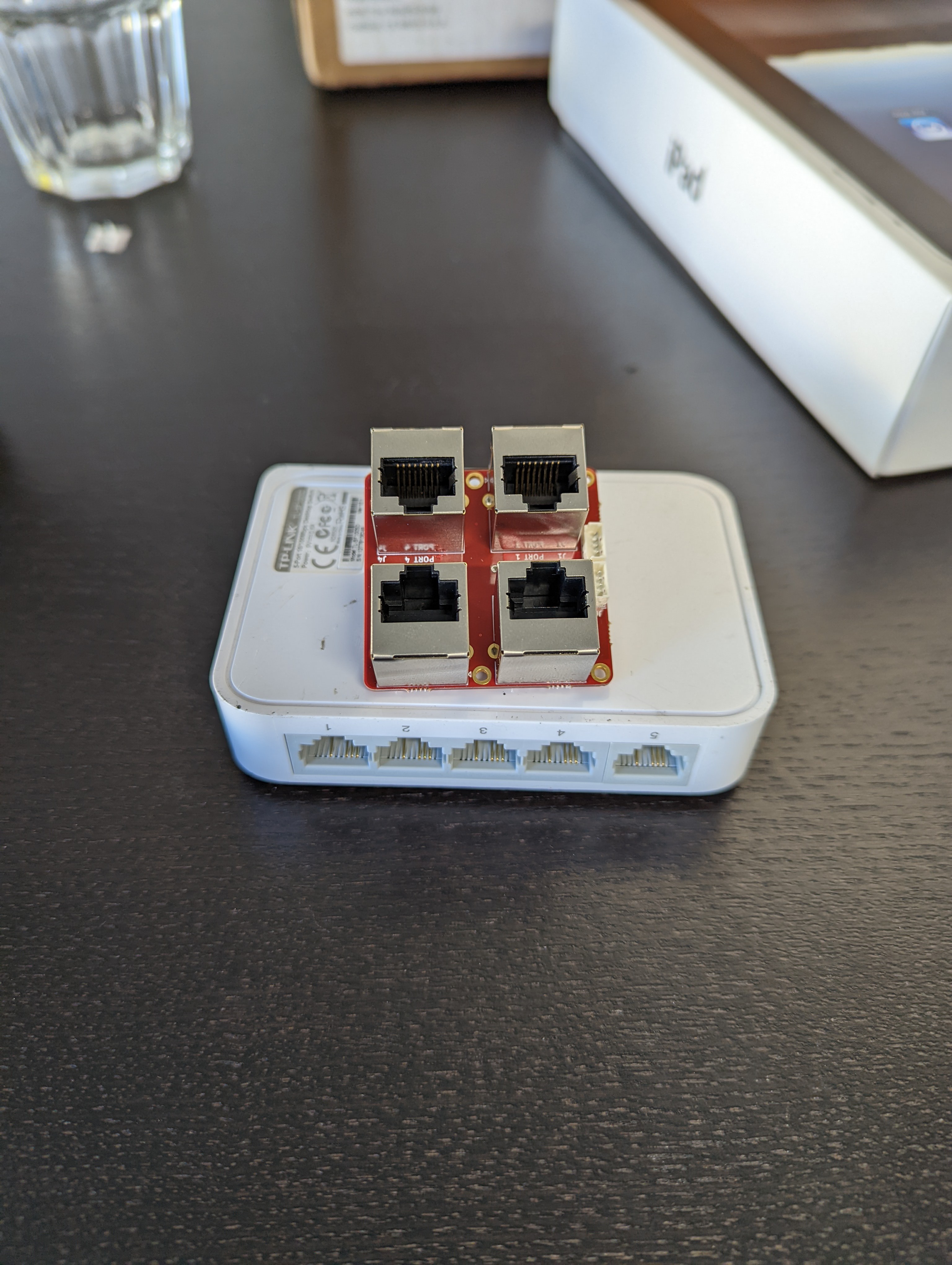
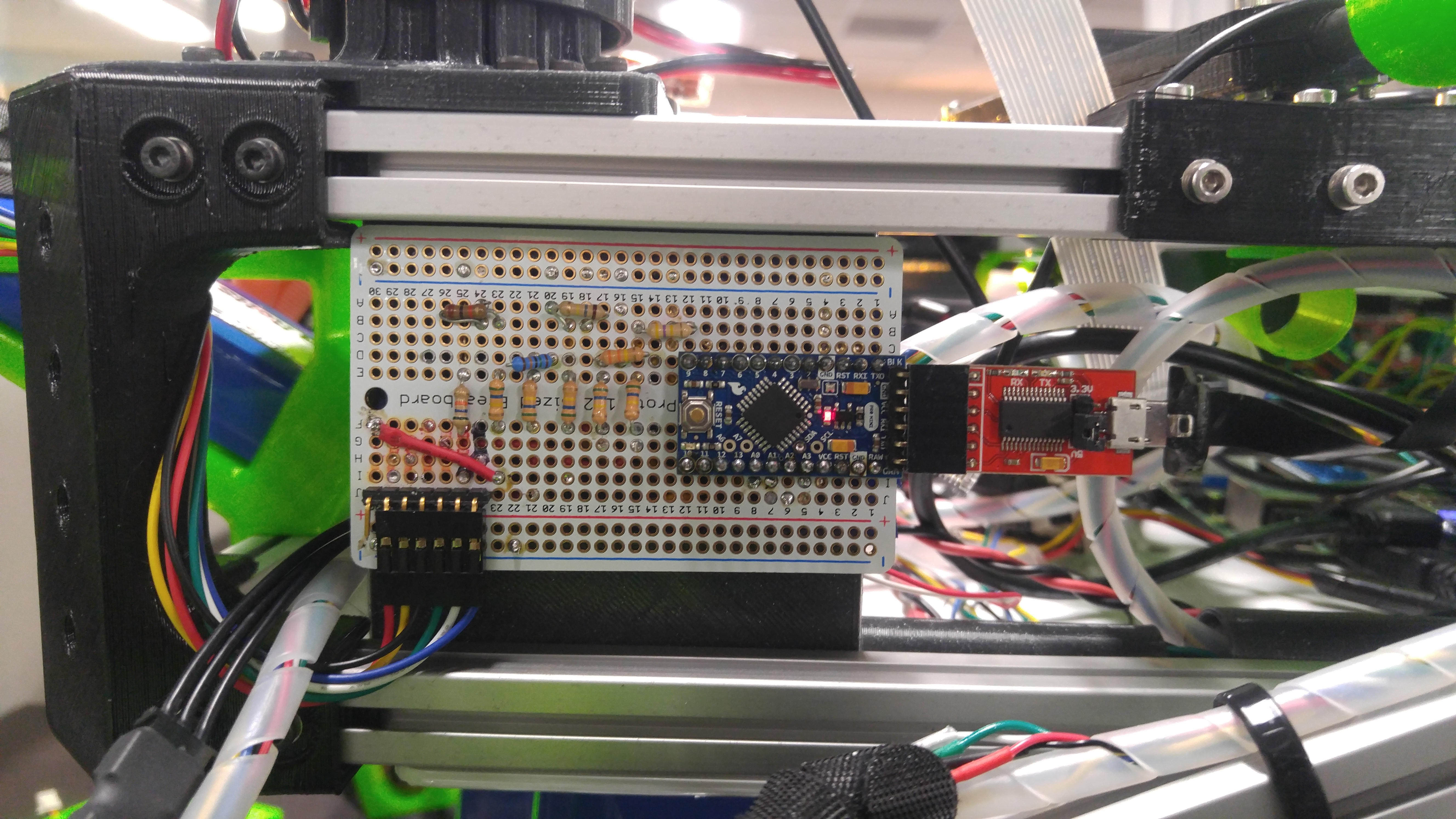
    Here's what that looks like when put down on a breadboard:
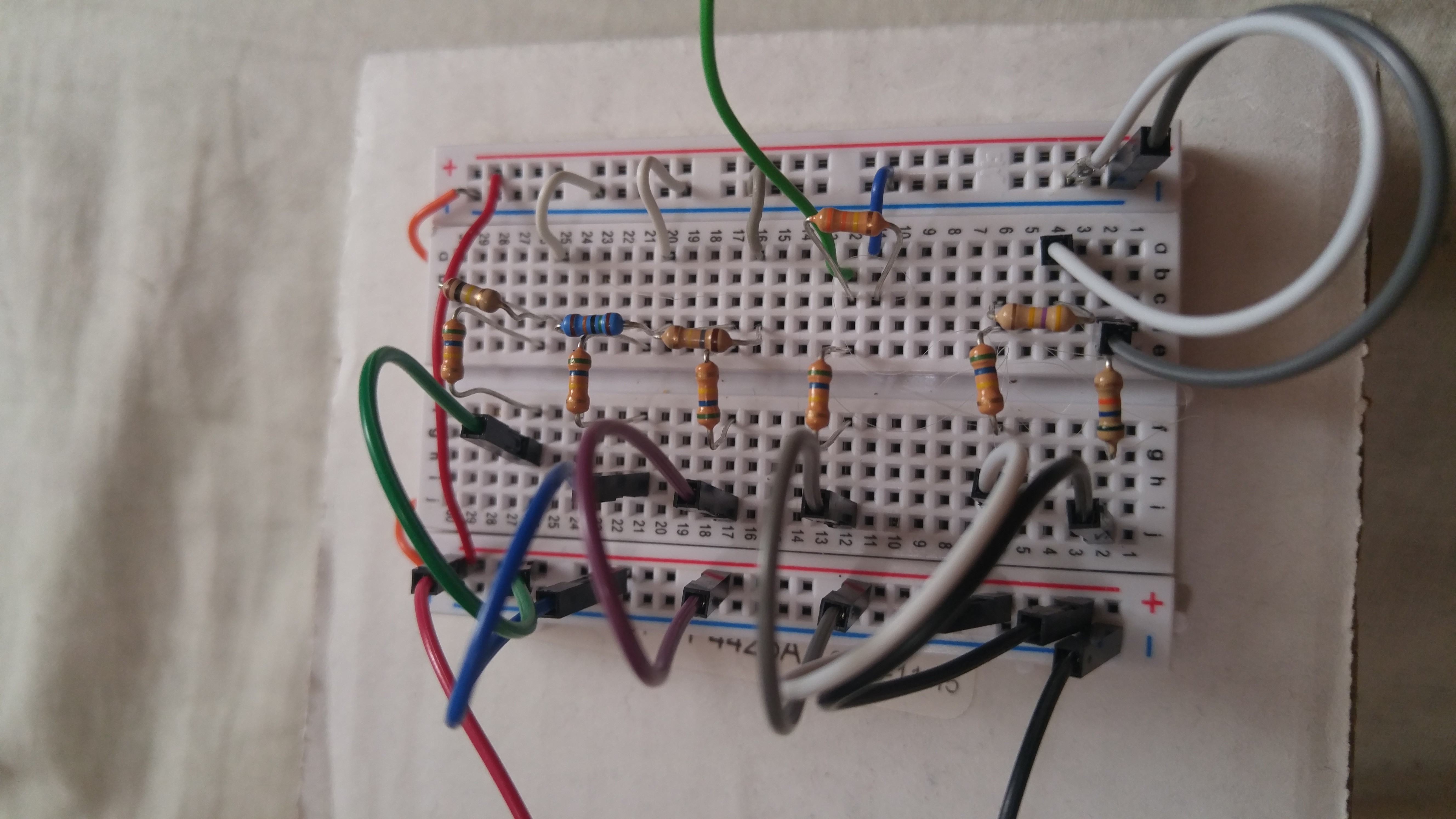
    and the final realization installed on Tenacity, complete with readings off an 11.1V 5000 mAh LiPO battery shown as a ROS topic.


    My hat's off to Duncan Iglesias over at Instructables for the neat circuit!
    Now I can send Tenacity roving near and far and keep track of when it's time to bring it home for a charge :)

  • Quarantine CAD

    Steve06/01/2020 at 06:51 4 comments

    Here's some screenshots of some of the CAD I've been working on over the past month or two, while stuck inside because global viral pandemic.

    Let's walk through a couple things in this image so you can get an idea of some of my plots and plans for when I can get back to working on Tenacity.

    First we have these "sensor stalks". The one with the flat top is what's currently mounted on the rover. I'm playing with different angles on the top to incline a camera or LIDAR and give it a better view of the obstacles in front of it vs. seeing things at knee height and missing things underfoot. The one off to the left in the back is inclined 15 degrees. The one in the front is tilted 10 degrees.

    As much as I've tried to keep the cable plant under control with twisting and flex-wrapping the cable bundles, velcro-ing and routing them along the corners, it's becoming obvious that I'm going to need to add an additional "equipment deck" above the top of the body box. The original impetus behind this was to have a place to mount a Jetson TX1, but the more I worked out what the compute and vision-processing system would look like, the more I realized I just plain needed more space.

    So here's a quick sketch of what that might look, modeled in a mix of OnShape and OpenSCAD.

    The bracket is slotted for a length of 1515 to be inserted to support the weight of the additional hardware mounted up top.

    Finally, we come to this bracket here, which has been showing up in most of the images here and should be recognizable by most Sawppy Builders as the bottom part of the differential holder. When I was building my Sawppy last summer, I became rather captivated and inspired by this particular piece. I really liked how it fit into the upper part of the differential and how it clamped onto the crossbar. So I "repaired" the holes in Onshape to make it a universal mounting bracket.
    I'll upload these to my GitHub fork of Roger's Sawppy repo in case anybody finds them useful.

  • On the road again!

    Steve03/09/2020 at 13:56 0 comments

    Tenacity is back on the road!(carpet), fresh from what turned out to be an almost 3 month(-ish) refit. 
    A good bit of consulting work came barrelling out of nowhere right after the start of the New Year, so I've spent most of the past couple months taking care of the funding that makes this rover roll. "No bucks, no Buck Rogers" as a man once said.


    One thing that kept breaking last fall was the keypad that was part of the chording keypad teleop control. Replacing that meant getting serious about a proper control system, which led to a complete rewiring and internal reconfig, but overall a much more complete rover and much closer to an actual completed first rev platform.

    Current config is:

    • Raspberry Pi 3 running ROS Kinetic from Ubiquity Robotics ROS Distro.
      • Replaced the ArbotixM Dynamixel controller with a USB2D USB-based controller.
    • Arduino ATMEGA 2560 with a screwdown shield board to deal w/ all the pins from the 6 motors.
    • L298N motor controllers
    • Jetson TX1 to run the depth camera, although I'm working on getting that to run on a Pi 4 because of the smaller physical footprint.
    • Orbbec AstraPro depth camera
    Software:
    • ROS Kinetic, largely because the peripherals I want to connect to Tenacity just work out-of-the-box and it's still got a year to go on its LTS. I'm admittedly being impatient but really just wanted to get my rover rolling on a software stack and come back to updating it later.
    • My own "Hackermann" steering package to handle the corner steering.
    • I've managed to be able to keep much of the Arduino motor control code throughout this entire refrob, so the basic L298 inteface code I wrote last summer is still there.

    Materials

    Most of the NylonX parts have snapped at this point. The suspension for the rocker/bogie assembly have been replaced with metal. The surviving  parts are all the shorter or thicker bits like the motor couplers and drive shafts.  The last of the steering shafts broke last weekend when Tenacity got rear-ended by a runaway DonkeyCar.  This has provided me with an excuse to open a spool of polycarbonate (PC) and print off some replacement parts. We'll see how these fare compared to the nylon.   I will do a longer post about the whole 3D-printed structural adventure and all the different materials I've tried at some point in the future.


    TBD:

    -Get working on vision and navigation now that I have a driveable rover.

    -Add power management support via an INA219 so I can get some sort of software visibility into the overall power consumption of the whole system and from there individual components.

    -Sonar and maybe some bump sensors "for better hallway vision".

    Anyway, that's an off-the-top-of-my head update on what's going on with Tenacity. Post below if you have comments or questions.