Close
0%
0%

74HCT6526

Building a Drop-In Replacement for the MOS6526.
Sponsored by PCBWay

Similar projects worth following
Just out of fun and curiosity, I started in August 2018 to analyze, dissect, study, comprehend, and replicate using 74xx logic ICs the MOS6526, also know as CIA, used by many Commodore computers.

This project is now sponsored by PCBWay.

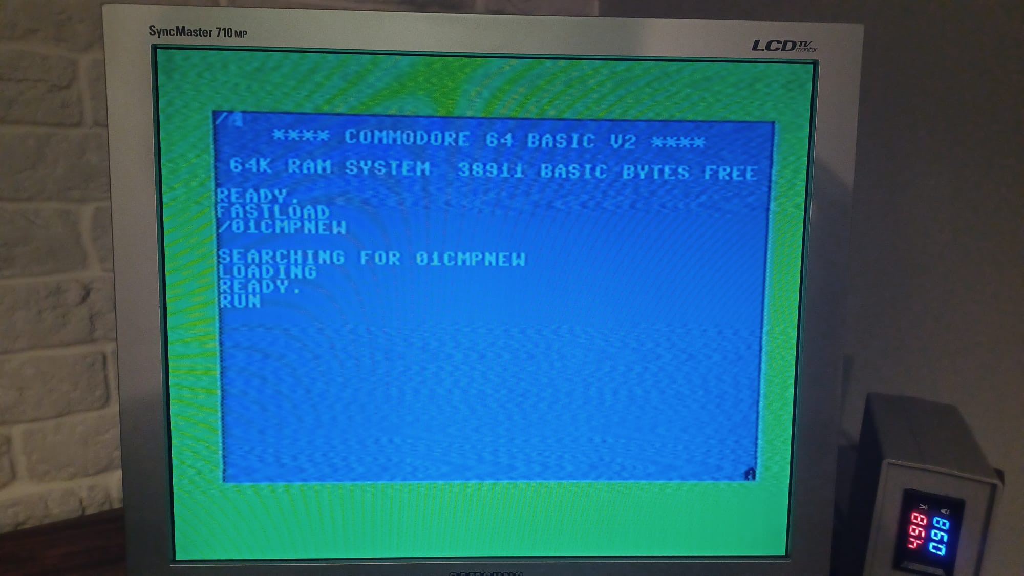
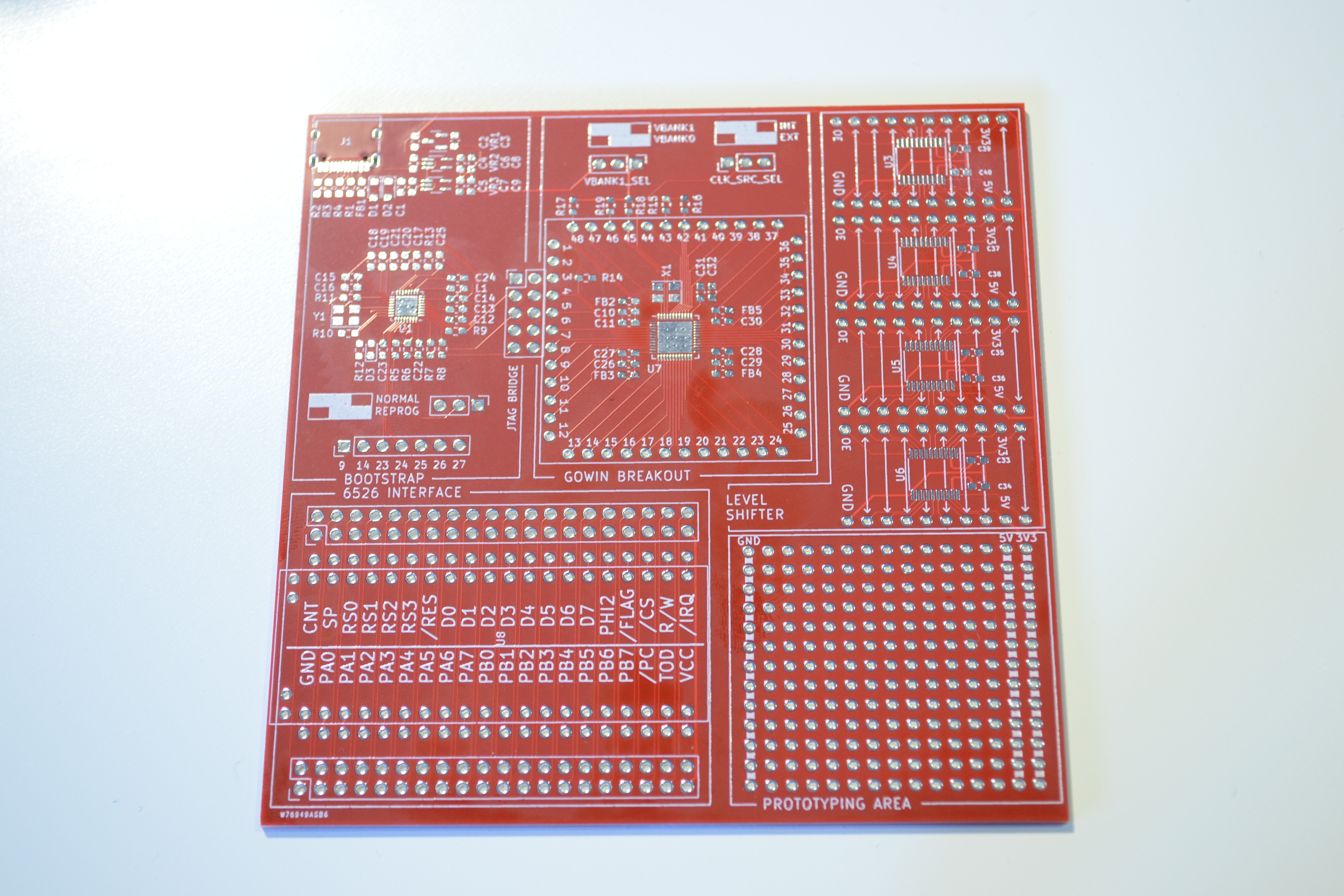
Inspired by the https://c74project.com/ the goal of this project is to build a drop-in replacement for the MOS6526, also know as CIA, used in many home computers by Commodore.

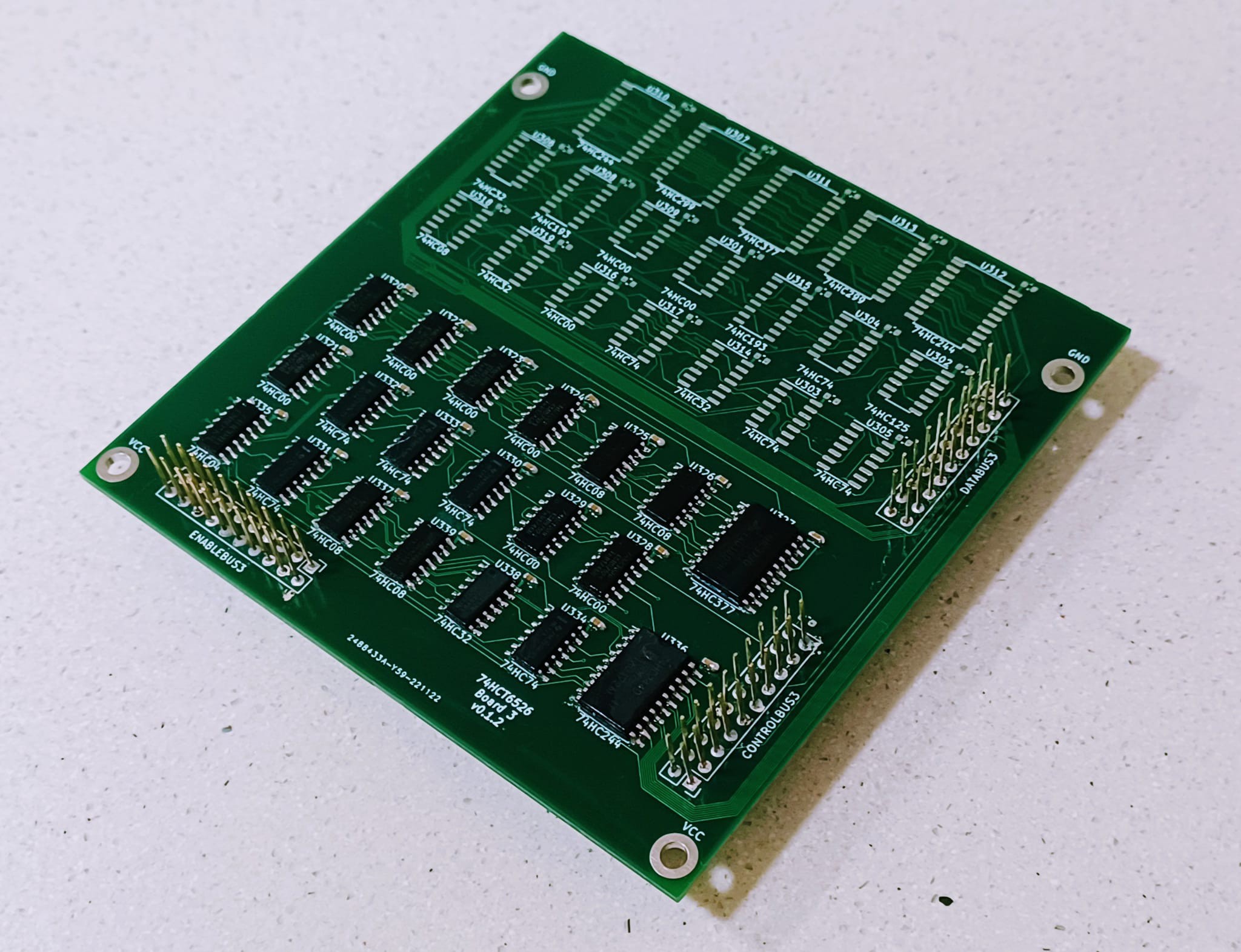
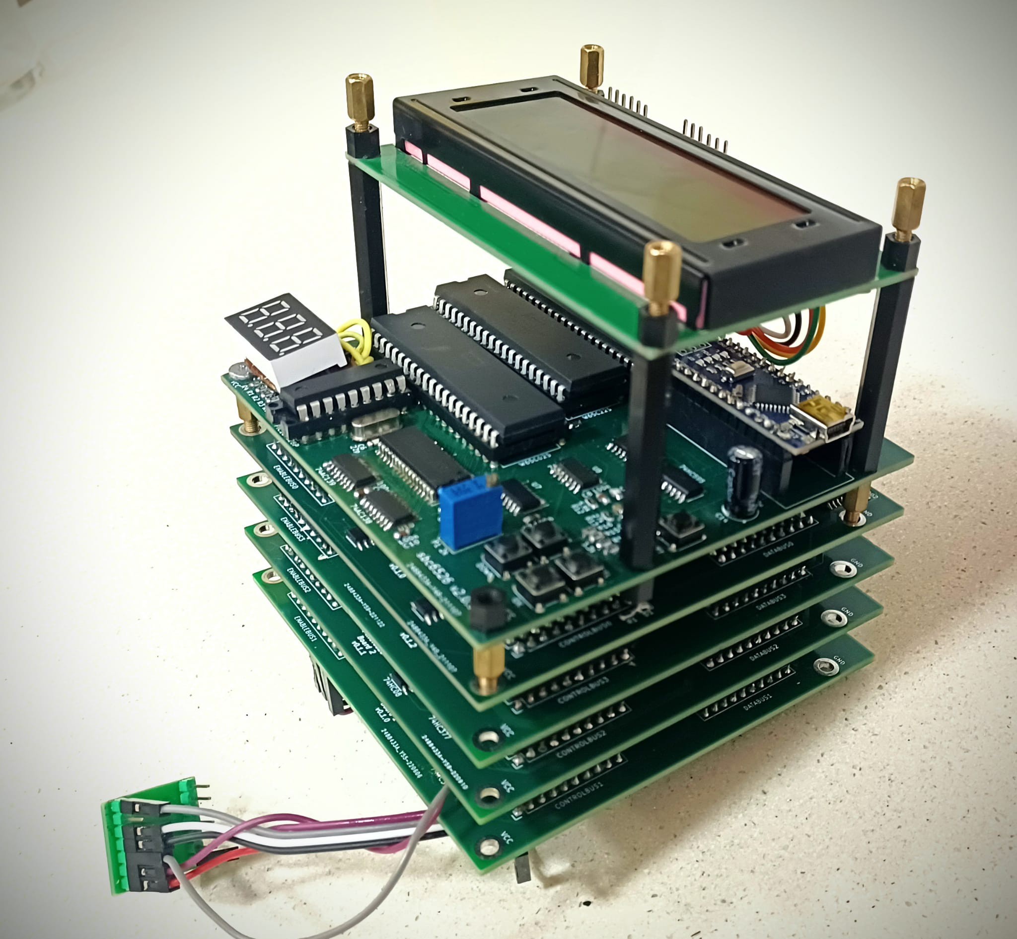
The final design aims to be build out of 5 boards:

  • Board 0: DDR and PORT
  • Board 1: Timer B
  • Board 2: Timer A
  • Board 3: TOD
  • Board 4: SDR and ICR


Board 0 will also include the main computer interface, so it will include a connector to be attached to the computer itself.

There are 3 vertical buses that will extend over the 5 boards carrying different control signals:

  • ENABLEBUS: The 4-bit address selector is decoded into 16 individual enable signals, one for each register
  • DATABUS: The 8-bit data bus from the computer, plus some other neccesary signals
  • CONTROLBUS: Different control signals that are exchanged between registers

  • Almost there

    Daniel Molina05/14/2023 at 16:45 0 comments

    As this project is nearing its fifth anniversary, some celebration was in order. But before that, I needed to make it look prettier.

    What you are looking at is B3. It houses both ICR and SDR and is both the densest packed board and the trickiest one to get 100% correct. You can see there are several connections amended, but it was for a good reason.

    The 74HCT6526 is now passing some tests of the VICE Test Suite. This is a nice indication that it is cycle-exact! I can also switch it from OLDCIA to NEWCIA with the flick of a switch.

    There are still some tests that are failing, but I'm pretty much there.

    Also, B4, housing TOD, has been completely designed now. We're still waiting for production though.

    Stay tuned!

  • Latest release is out!

    Daniel Molina01/25/2023 at 06:30 0 comments

    Today I'm releasing v0.2.0 of the 74HCT6526. There are plenty of small fixes, some issues with the SDR are sorted out, and the overall design has received a little and well deserved clean up. A change to the controlbus triggeres a jump in the minor release number (My current versioning scheme is MAJOR.MINOR.REVISION).

    This means, new boards are not 100% compatible with earlier ones. For a stack to work property, all boards should share the same MAJOR.MINOR version.

    You can find all details at my gitHub repo :https://github.com/dmolinagarcia/74HCT6526

    Now, work begins on the TOD, the last unit of the CIA!

  • Hello, I'm a SDR

    Daniel Molina01/20/2023 at 22:42 0 comments

    Or Serial Data Register. Even though it may be not very well known, it was meant to provide fast disk drive access on the Commodore 64 and Commodore 128.  But for classical Commodore reasons, we were stuck with the old and slow bitbanging IEC method. 

    Anyway, the 74HCT6526 now has a fully functional SDR. Now, only TOD is missing

  • Please welcome the ICR to the family

    Daniel Molina01/13/2023 at 09:29 0 comments

    I want to introduce you to the newest member of the family.

    B3, with ICR fully populated. The upper half of the board is the SDR, but I won't be soldering that in until ICR is validated. There are a couple of expensive ICs there (Two 74299 shifters) which I'd rather not to solder until I know the ICR works fine.

    And... to my great surprise... it does. I've been only able to do some minor tests, as I finished assembling the ICR just a couple hours ago. So far :

    • Interrupt mask can be properly set and cleared.
    • Timer A and Timer B interrupts work, and I'm proud to say, the appear cycle exact!
    • Flag interrupt it's not working for some reason. Could be a a bad connection or solder joint, as at first glance, I see nothing out of place in the schematic. Further investigation is required.
    • TOD and SDR interrupts can't be tested yet, as there's no TOD or SDR to be fire the interrupt. Hope are high, given the circuit for them is pretty much the same as TA and TB
    • Timer B bug will require extensive testing. Theres a 50/50 chance of it being "fixed". If I've managed to replicate it, I'm afraid I will also have a Timer A, SDR, TOD, and FLAG interrupt bug. 

    This is truly a huge milestone. I will test as soon as possible the full stack on a real C64, as now I have pretty much everything needed by the computer to work properly. TOD, SDR and Flag interrupts are not used a lot. 

    Today, after 4 and a half years of work, I'm 99% sure this project will succeed!

    Cheers!

  • Finally, we're moving on

    Daniel Molina10/03/2022 at 09:13 0 comments

    B2 PCBs and components arrived a week ago, and it's now complete. B2 comprises TIMERB and CREGB and, with the lessons learnt in B1, everything worked beautifully on my first try.

    TIMERB counting TIMERA underflows works, and I only need to determine it this is cycle accurate compared to an original 6526.

    Meanwhile, design for SDR and ICR is mostly done. Hopefully, it will be built and tested before the end of year.

  • PCBWay and fast prototyping

    Daniel Molina09/12/2022 at 19:37 0 comments

    As I get to the most complicated parts of the 74HCT6256, such as the Serial Data Register, or the Time Of Day set of registers, the amount of logic required to mimic the behaviour of the original MOS6526 increases. 

    Luckily, as my skills are improving, I'm managin to cram more component on each board. Proof of this is that the two remaining boards will have more ICs combined than the first three.

    However, as complexity increases, so does the mistakes in the design. I've choosen to take a shortcut, and go the FPGA route for development and testing. This way, I can try and test many design, without the need to order, build, and test new boards each time.

    To do that I needed a small setup. with a FPGA, it's programming hardware, and the ability to rearrange all connections as needed, including voltage level shifting, and prototyping space.

    Thanks to the leading PCB manufacturer PCBWAY, I've managed to get some PCBs manufactured. And the requirements where pretty high! Some spacing were the smallest I've ever worked with, with 0.4mm pitch in some components. 

    This is what the full (unpopulated) board looks like.

    The smallest details are incredibly accurate:

    Solder mask alignment was crucial and PCBWay got it spot on. 100% accuracy.. Those footprints on the sides of the main IC are 0603 SMDs, so imaging how tiny the space between the pads of U7 is. Vias in the picture have a 0.2mm drill hole, which is the smallest you can go. Vias on a pad? Oh yeah, no problem! 

    Being my first board with this requirements, It had some minor mistakes. Communication with PCBWay engineers was fast, efficient, and helped my getting a perfect result. In the then, less thay 24 hours went since I uploaded the design, to manufacturing completion.

    There are cheaper alternatives to PCBWay, for sure, but you usually get what you pay for. If you need very small features, tolerances, and assurance that any mistakes on your board will be detected beforehand, PCBWay for sure can handle it. 

    Silkscreen quality is also close to perfection, with even the smalles details showing barely any blurred edges, aligment issues, or any other kind of problems.

    And, by the way, if you spot an arrow in the left missing half of his head... that's an issue in my design, as I inadvertently deleted that bit. Ouch!

    In the end, after a fast production, I had the board at home within a week, ready to give the development of this project a big push. Thanks PCBWay for this!

  • TIMERA is now cycle-exact

    Daniel Molina08/11/2022 at 07:50 0 comments

    Just a quick update for today. After two weeks testing and debugging TIMERA, I can now say it's a cycle-exact replica of a real MOS6526 timer. 

    Moving on to TIMERB!

  • Three years gone...

    Daniel Molina07/26/2022 at 19:32 0 comments

    Almost three years since my last update. Work hasn't completely stop at any time, but for sure, efforts have been kept very minimal. 

    Anyway,  after a major redesign of the whole stack, I'm pretty much at the same point I was 3 years ago, with just one little difference... now my timers do work.

    This is the new Board 1. TIMERA plus CREGA. I just finished building it like 5 hours ago, and it still needs some thorough testing, but so far, it's very promising. 

    Stay tuned for some more news very soon. If everything works as expected, progress is going to be very fast now.

  • Once upon a time, there were two little TIMERs...

    Daniel Molina10/12/2019 at 21:30 0 comments

    I've spent quite a few hours this weekend here

    It's starting to look a lot like my bedroom when I was a kid, not sure if that's good or bad though...  :D 

    Using a small piece of assembly that took me 2 hours to complete (I've got so rusty)

    I've been able to try plenty of stuff. There are some things remaining that will need some heavy use of my logic analyzer, as timing's crucial.

    The good news so far :

    • Starting values. Timers' latches should be set to 1, control register to 0. Big facepalm here, as I completely messed up the schematics, a (very much) needed inverter is missing. As a consequence, Timers' latches are perpetually set to 1. Some PCB hacking has been done and, now they initialize with rubbish, but at least I can write to them. An easy fix for rev 2. Control registers initialize OK
    • PB7 and PB6 override. Setting the bit in the control register forces PB6 and PB7 as outputs. 
    • Timer reloading from latches. Works fine, whenever a write to the high byte with timer is stopped, whenever FORCELOAD is written with a 1 (which is stored nowhere), or whenever there's and underflow
    • Timer output on PB6 and 7. TIMERB toggle output works. Pulse output requires the logic analyzer to check. TIMERA output is completely missing. Circuits are the same for both timers, so could be caused by a bad solder
    • Timer B won't count Timer A underflows. Could be related to the above issue
    •  One shot mode. It works, timer counts down until the overflow happens, Then relatches the value.... but then it ticks once more before stopping. Same for both timers. 

    The untested bits:

    • Pulse output. 
    • CNT pulses counting
    • Different overflow behavior counting PHI2 vs CNT (4-3-2-1-4-4-3-2 vs 4-3-2-1-0-4-3-2-1-0)

    And the know issues:

    1. TIMERA underflow seems to fail. Could be a bad solder
    2. START bit gets set to 1 on its own sometimes. Same for both TIMERS. 
    3. Adittional tick in One Shot Mode. I think this is caused by the 2 DFF feeding the clock to the Timer. When Timer stops, there more clocks in the queue. I probably need to clear one of them when the underflow is reached.

    All in all... I'd say it's a 7/10 score so far. START bit has me scratching heavily my head... but I think I should better sleep on it. I've had no ideas about what's causing this so far.

    Cheers!

  • Poor old PHI2...

    Daniel Molina10/09/2019 at 20:52 0 comments

    Some quick tests, and I've managed to find the cause of the issues I was facing.

    See, this is a pretty much normal PHI2

    And this is PHI2, when I added the three boards.

    So awful!

    Of course, nothing running on PHI2 worked. Not CIA#1, not CIA#2,  probably not the SID, not even my 'thing'.

    This is caused by PHI2 being fed into too many inputs, up to 18. Old NMOS technology can't pull up fast and hard enough, so the rising slope of PHI2 was slowed too much.

    Adding a single non-inverting buffer to pass PHI2 through has been enough to fix the problem, and now I have all 3 boards working.

    Next task... prepare an intensive test suit for the Timers. There are just toooo many quircks about them!

    Cheers!

View all 14 project logs

Enjoy this project?

Share

Discussions

Dan Maloney wrote 09/25/2019 at 16:20 point

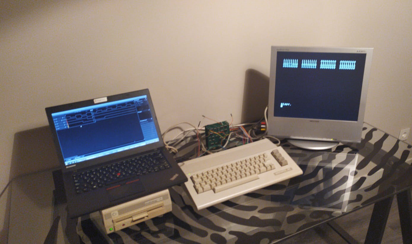
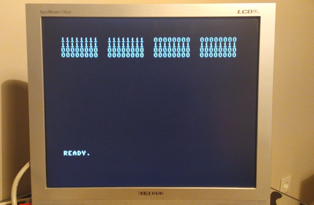
This is pretty cool. Looking forward to seeing the whole 5-board stack in action.

  Are you sure? yes | no

Similar Projects

Does this project spark your interest?

Become a member to follow this project and never miss any updates