To Do
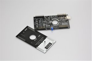
[Hardware]
- Complete Simulations of Output Stage
- Test Power Supply
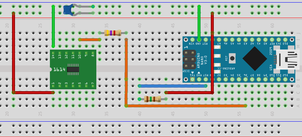
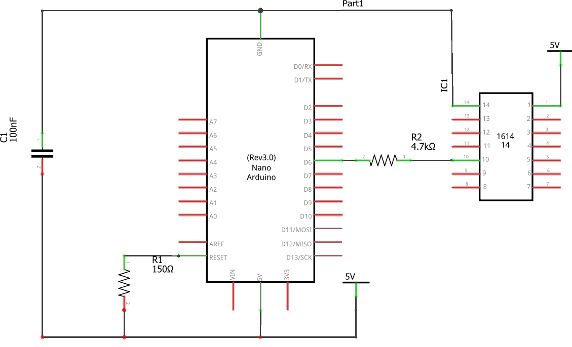
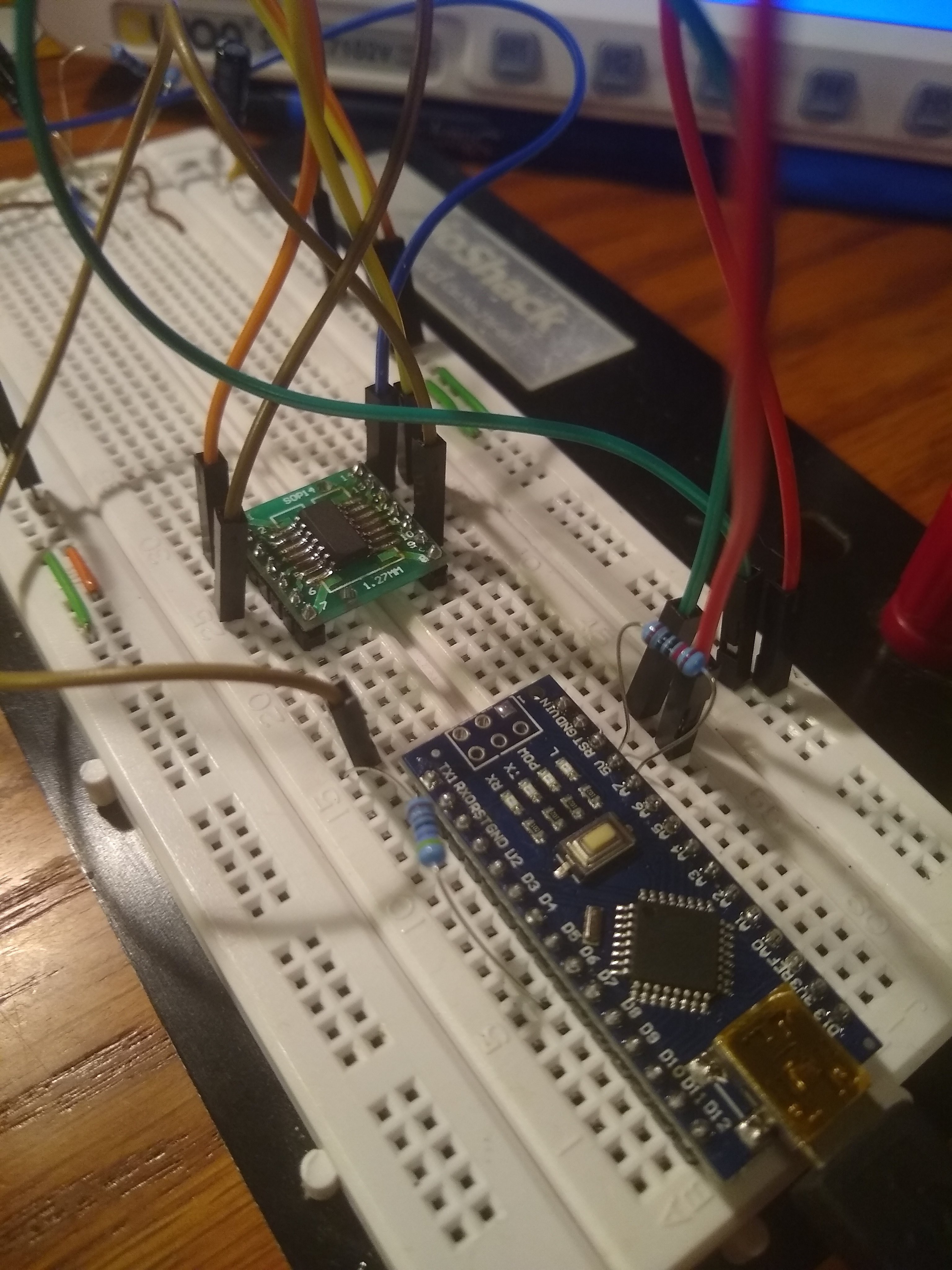
- Finish Prototype with MCU
[Software]
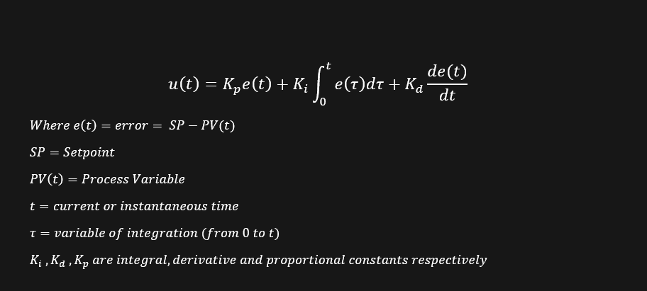
- Write PID loop software
- V0.1 of PID Library Uploaded
- Add mode selection for PID, PI, P controller types.
- Write interface library for display, buttons, encoders etc.
Changelog:
[Misc]
- Fixed broken GitHub Link
- V 0.1 of PID Library on GitHub [10/21/1019]
-----------------------------------------------------------------------------------------------------------------------------------
Useful Links
http://ww1.microchip.com/downloads/en/DeviceDoc/ATtiny1614-DataSheet-DS40001995B.pdf
http://ww1.microchip.com/downloads/en/Appnotes/TB3210-Getting-Started-with-DAC-90003210A.pdf
http://ww1.microchip.com/downloads/en/Appnotes/TB3209-Getting-Started-with-ADC-90003209A.pdf
-----------------------------------------------------------------------------------------------------------------------------------
Source Code:
[GitHub]
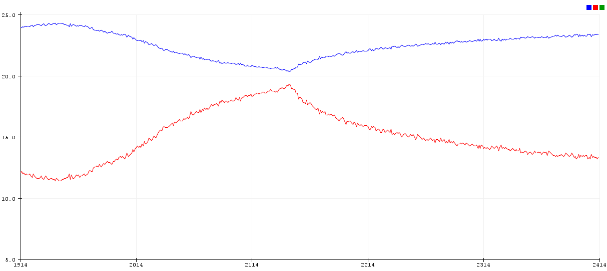
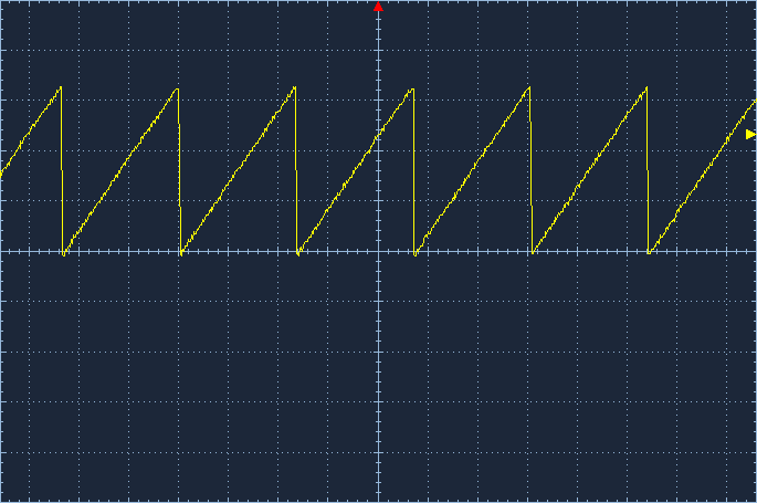 Unfortunately, the DAC can only go up to 4.3 V, so I will have to include some sort of compensation if I want true 0-5V output.

 Benjamin Prescher
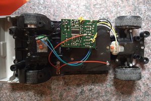
 Blake W. Ford
 Pedro Minatel
 AndrewMcDan
I like the idea of plug-and-play PID. How will you provide for loop tuning? Directly on this board, or through whatever host you wire it into?