Hello everyone!
It has been a bit longer than I wanted between project logs, but I have managed to make some progress, while learning some important lessons. Upon trying to program the ATtiny 1614, I realized that the old ICSP programming method was not going to work. The ATtiny 1614 is a tinyAVR-1 series MCU. This means that they use a new proprietary method called UPDI. It is nice because it uses fewer pins, but I did not own a programmer for UPDI, and was not going to pay for an expensive Atmel ICE programmer.
Instead of buying a programmer, I made one using an Arduino Nano clone using jtag2UPDI, a piece of firmware that essentially turns an Arduino Uno, or any ATMega 328 MCU into a UPDI programmer. It was pretty simple to set up, both software and hardware.
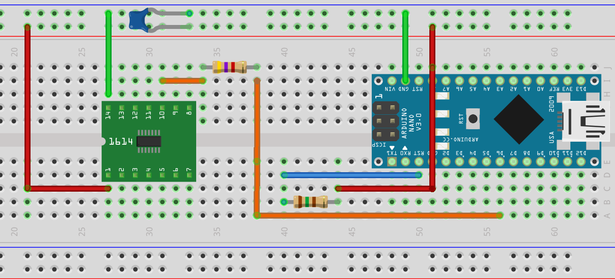
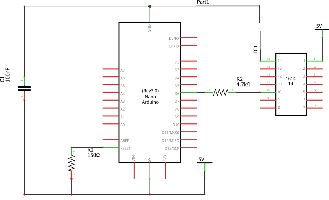
As seen above, the breadboard layout is pretty simple. I connected D6 on the Nano to Pin 10 on the ATtiny 1614 through a 4.7 KΩ resistor. Then I connected VCC and Ground on pins 1 and 14 on the ATtiny 1614 respectively to +5v and GND on the Arduino. Last, I added a decoupling capacitor (0.22uF), and a 120Ω between RST and +5v to disable the reset. I followed the setup instructions to load the jtag2UPDI firmware, and was ready to program. I might post a tutorial on this later, to take you though all of the steps in detail. There is a schematic view of this below.
For uploading code, I opted to use the megaTinyCore for speeding up development by allowing me to use Arduino code to write the programs. This greatly simplifies things, as the documentation for the ATtiny 1614 is a bit hard to understand, and most importantly, rather disorganized at the moment.
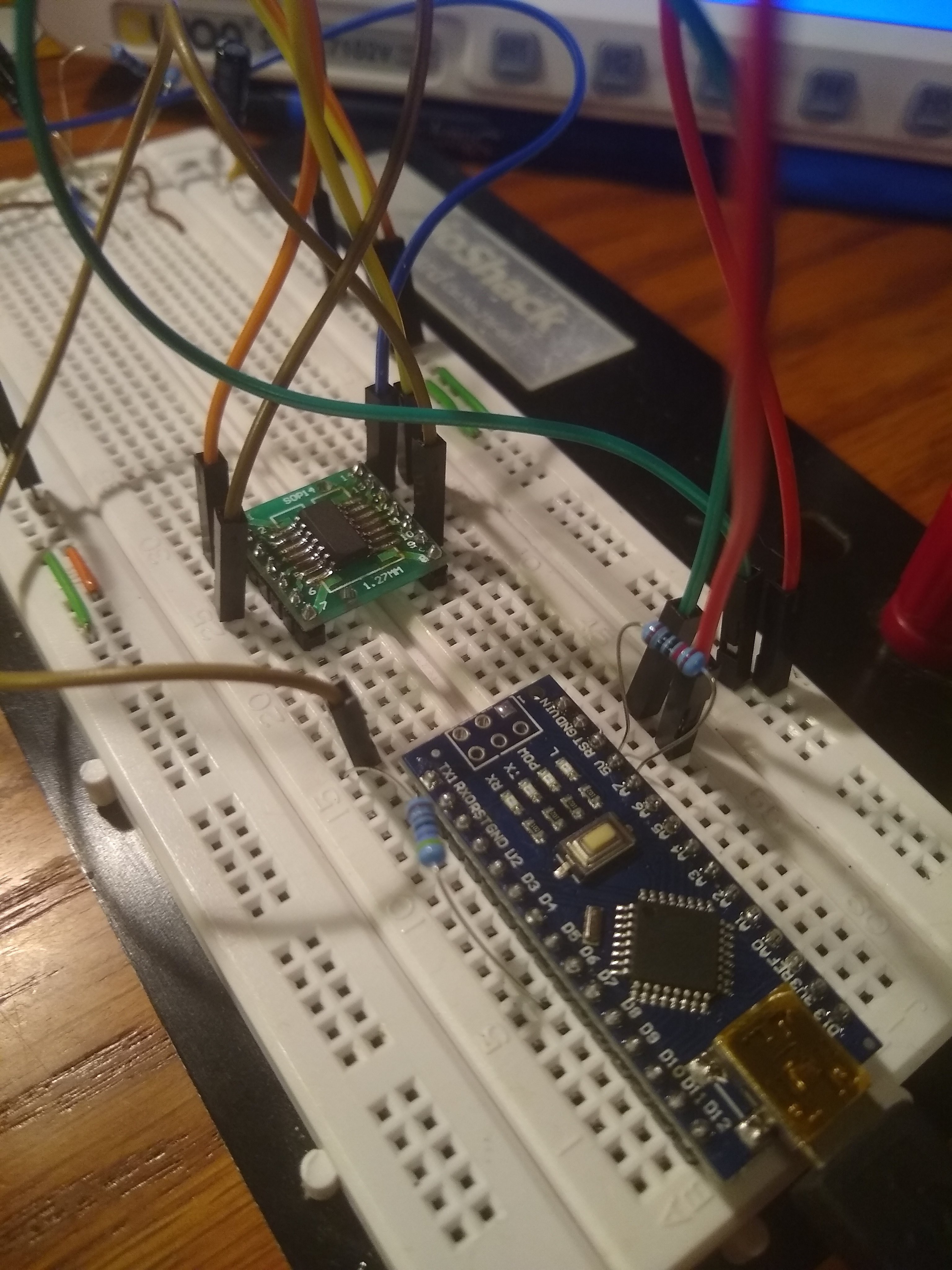
Here is the setup that I am currently using for programming. I had it soldered to perfboard initially, but messed up, and haven't had time to fix it yet, so it remains on the breadboard for now.
So far, I have been learning how to work with the ATtiny 1614, I have so far been able to program via Arduino, as well as Atmel Studio, and am just working on basic tasks. I have GPIO working, and with some mild frustration, have the DAC working as well. I was able to get the DAC to generate the waveform seen below. Seen here at (1V/DIV) at a frequency of about 2.13 kHz.
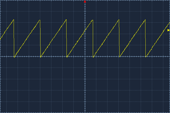 Unfortunately, the DAC can only go up to 4.3 V, so I will have to include some sort of compensation if I want true 0-5V output.
I hope this update was not too long, but it contained a lot of information. I can now focus more on the program side of things, now that I have some working hardware. As always, feel free to comment if you have any questions, comments, or suggestions.
Discussions
Become a Hackaday.io Member
Create an account to leave a comment. Already have an account? Log In.