 sjm4306
Here's a quick demo and assembly video that recaps the hardware side of things:
Ok, with that out of the way we'll now go into some more detail about the software works. The software has a few main tasks going on that all have to run simultaneously. First the atmega328P has to generate the higher voltage for the tube and it does this using timer1 running at ~62.5kHz (adjusting the duty from 50-95% will boost the open circuit voltage from ~30-120V, respectively). Luckily the load (the vfd tube) wont really change drastically during operation so I just run the boost converter open loop, although closing the loop would be simple enough by adding some code to the interrupt.
Additionally we need a method to automatically update the multiplexing to all the digits. This is done in the timer2 interrupt which is configured to fire off at 2kHz. In this interrupt we do a couple of things. First off, similar to my word and discrete 8 digit LED clocks, the interrupt will step though one digit each iteration and set the correct segments to send. Data is sent serially via the SPI peripheral so that we don't have to waste time manually bit-banging pins to send the required 20 bits to update the next digit. Actually an odd aside, since the mcu only deals in 8 bit spi packets at a time we end up having to send 3 bytes (24 bits) and the first 4 bits just end up being discarded.
So now we have high voltage and data going to the tube driver. All we have left to do is read button inputs, talk to the real time clock and make fun beeps/boops when a button is pressed. I originally wanted to generate the beeps of adjustable frequency using timer0 but found out that's what the arduino library uses to generate delays and messing with that would be slightly annoying. So instead I just look for a buzzer flag that any function can set to control the buzzer and if it's set then in the interrupt it toggles the buzzer pin. Since it can only toggle it once per interrupt period then the frequency ends up being half that of the interrupt which is 1kHz (a suitably loud but not too annoying frequency for a beep).
The real time clock is also controlled via SPI, but I was a bit lazy on this one and just included the library file I wrote before for bit-banging the signalling (I definitely could have shared the data and clock with the max6921 driver chip though and just given the rtc a separate chip select). We have lots of free pins so why not.
For the button pins, I thought of having a separate pin change interrupt to read them, but instead I simply reused the timer interrupt to poll the buttons at 2kHz and set global flags which any other function can use to react to button presses. Additionally the button flags are also read during the buzzer code in the interrupt to beep when any button is pressed for a bit of user feedback.
So that's about everything in terms of software. There is one major bug I've found where segment A of digit 0 always seems to be set and I've tracked it down to the display mux code in the interrupt so I'll fix that once I get the time.
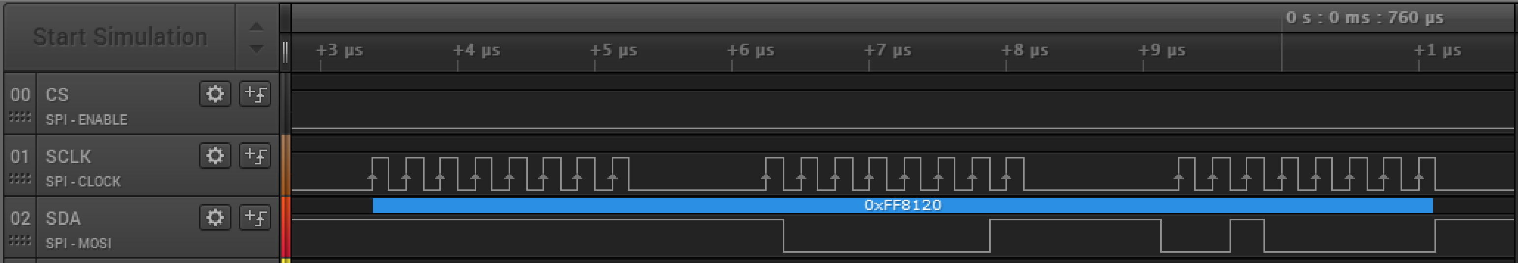 Oddly something is setting the first byte of the SPI packet only for digit 0 (It's 0xFF here but should be 0x00). Anyway once I squash this bug I'll upload all the design files to the project page.
[Edit] I've narrowed the bug down to something errant in my code overwriting just the A segment bit only for the 1st grid. By manually clearing the bit only when a character is displayed on the 1st grid that doesn't require it, everything is displayed correctly. I know this is a hacky way to fix this problem, but to the end user this fixes the graphical glitch and when I get enough time I'll properly track down and fix the root of the issue.
Discussions
Become a Hackaday.io Member
Create an account to leave a comment. Already have an account? Log In.