 Supercell
ARX MK0
This is the main variant of the ARX Hand Project which focuses on a bringing a fairly advanced low cost robotics hand design. This design is quite advanced and can be quite a challenge to build and use, as it involves close integration of motors and electronics to allow for function.
ARX MK0 Variants
- MK0M - https://hackaday.io/project/169585
An advance fully mechanically driven design with wippletree actuated fingers and 3 or 2 times mechanical advantage pulley system - MK0S - https://hackaday.io/project/169583
Servo variant which focuses on being an easy to develop robotic hand using standard servos which can be easily sourced and controlled - MK0PF - https://hackaday.io/project/173565
Figure variant which is non motorised and static design. Mainly focused for artistic uses such as in stop motion, display purpose, sketching, etc
Design Intentions
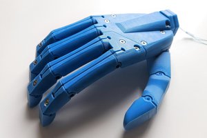
Many advanced myo electric prosthetic devices available in the market cost well over thousands of dollars which can be difficult for people to afford. ARX Hand Project hopes to create a highly affordable and easily producible motorised hand design with the help of modern low cost FDM printing and circuit fabrication facilities.
Design Aims
- Advanced motorised design
- Can be printed in with only PLA or PETG
- Easy to print - No supports needed nor any fancy materials to be printed
- Materials are easy to source
- Maintain good balance of functionality, ease of assembly and aesthetics
- Design is durable and is capable of withstanding impacts and drops
- Able to assist with lifting and grasping of objects
- Easily producible circuit design for low cost PCB fabrication and assembly
Design Summary
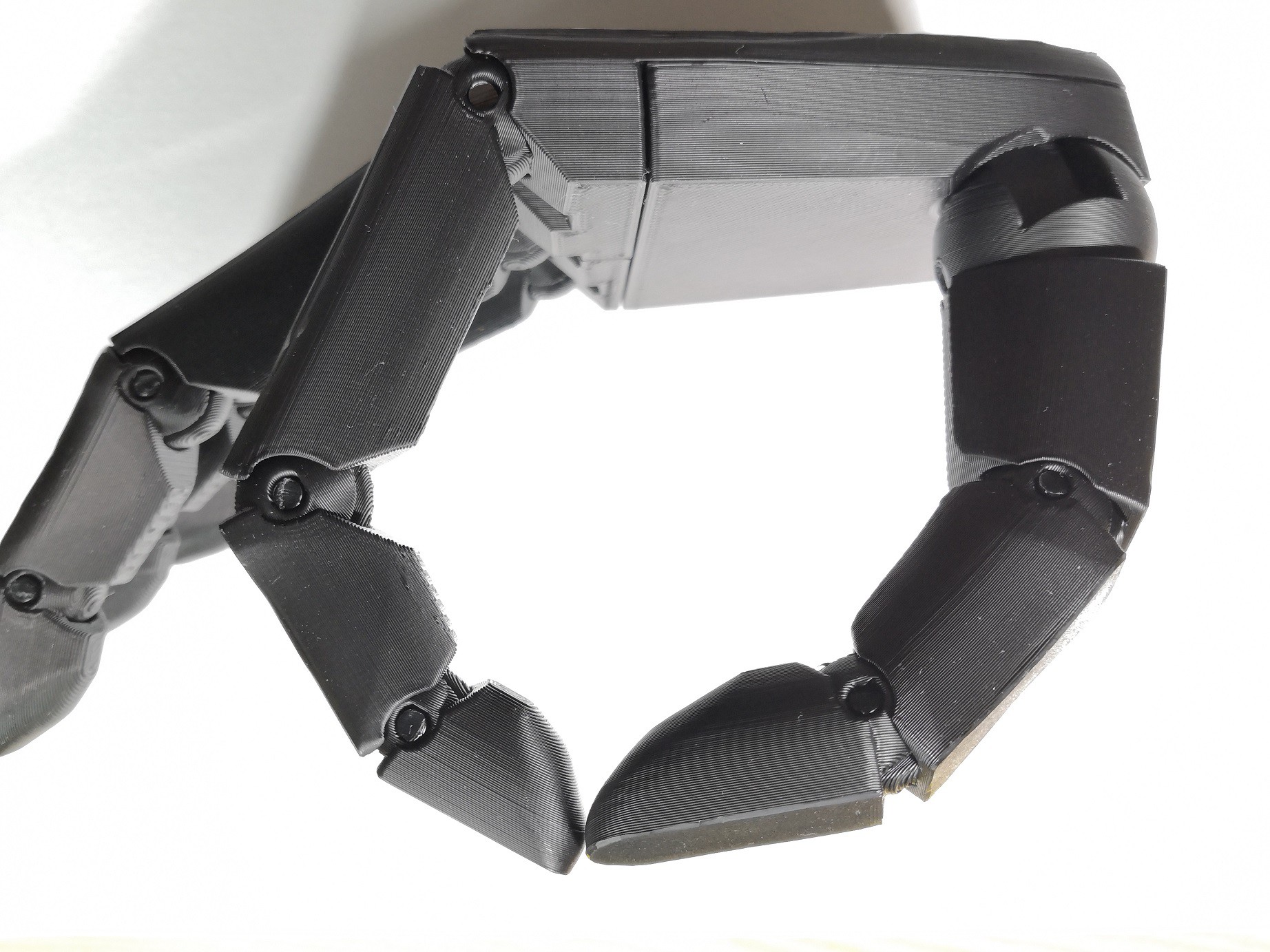
The design brings 5 degrees of actuation using motors along with 11 degrees of freedom in joints. It uses 4 micro geared motors which are controlled using a custom PCB and Arduino. Hand parts can be printed using any printer capable of printing PLA, and can be printed with or without supports. Additional materials required are some self tapping screws, 3mm nylon filament, elastic cord and 0.5mm to 0.8mm diameter braided fishing line.
Hand Design
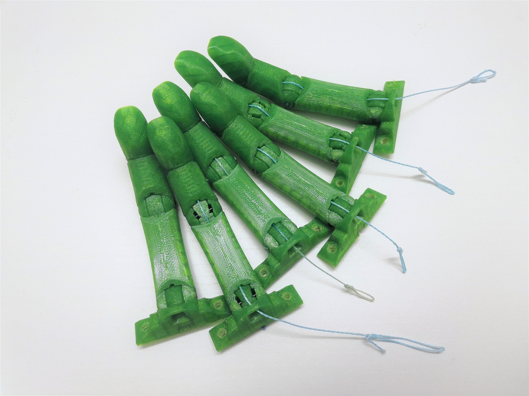
- V3.4 Finger Design
V3.4 builds on top of the initial design for V3 finger design. The aesthetic design remains the same, but many optimizations have been made to the design to improve overall printabilty and assembly.
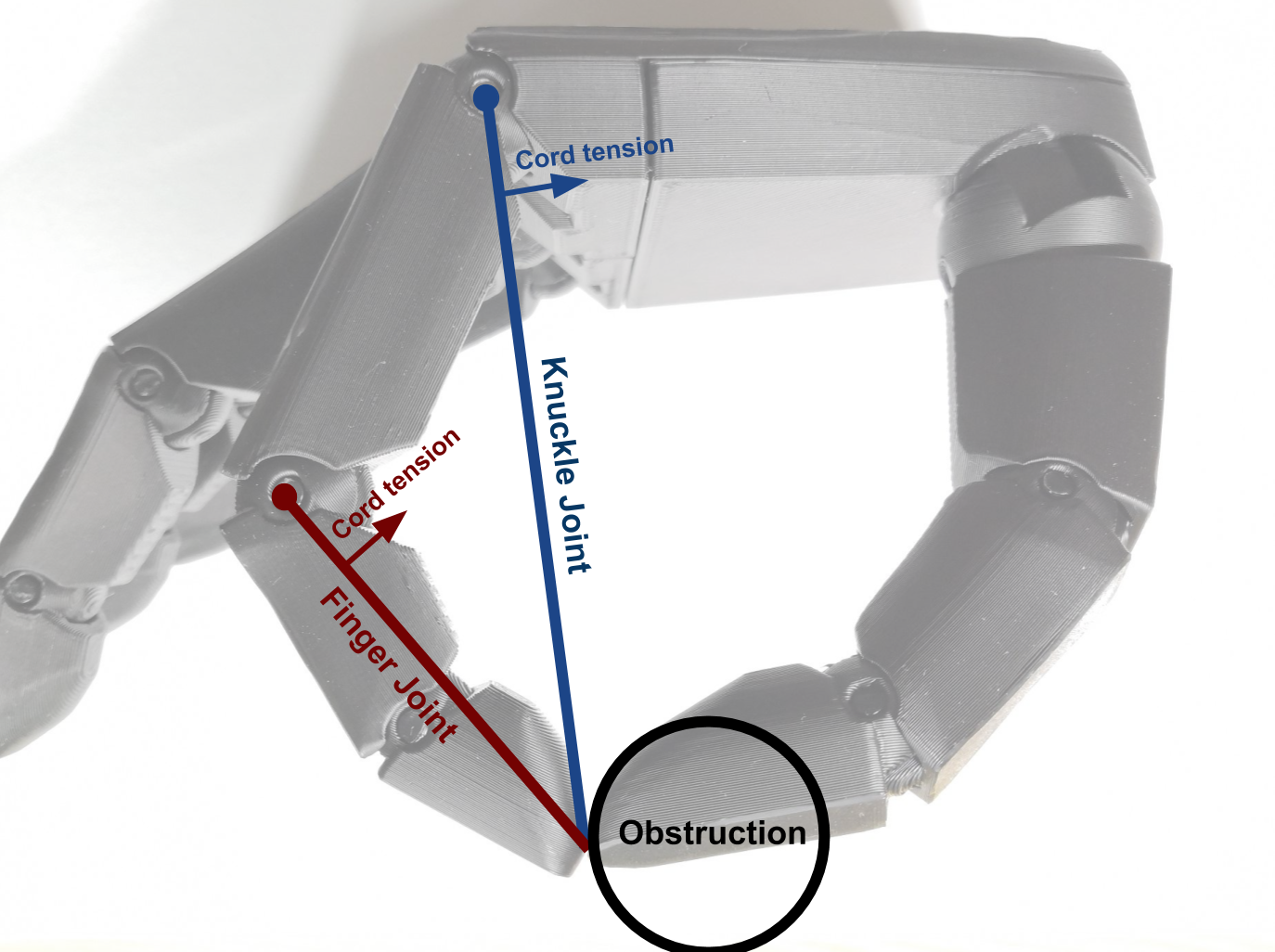
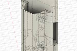
Subtle features have been added within the model to reduce effects of 3D printing imperfections from impacting the fitting of joints. Rounding to edges have been added to reduce overshooting artefacts on surfaces from ghosting, ringing and nozzle pressure build up. Seam adjustments have been added to avoid seams being placed between joint surfaces. Clearances on the joints are still fairly lenient to allow for easier printing, but clearances may be reduced down to 0.1mm if required.
For a two joint finger, fingers require the use of 1.75mm and 3mm nylon filament to act as pins between joints. Nylon should ideally be used as it provides a low friction, low wear joint. The flexibility of nylon also allows for a springing effect of joints, as well as to aid with friction fit joints through deformation of the material.
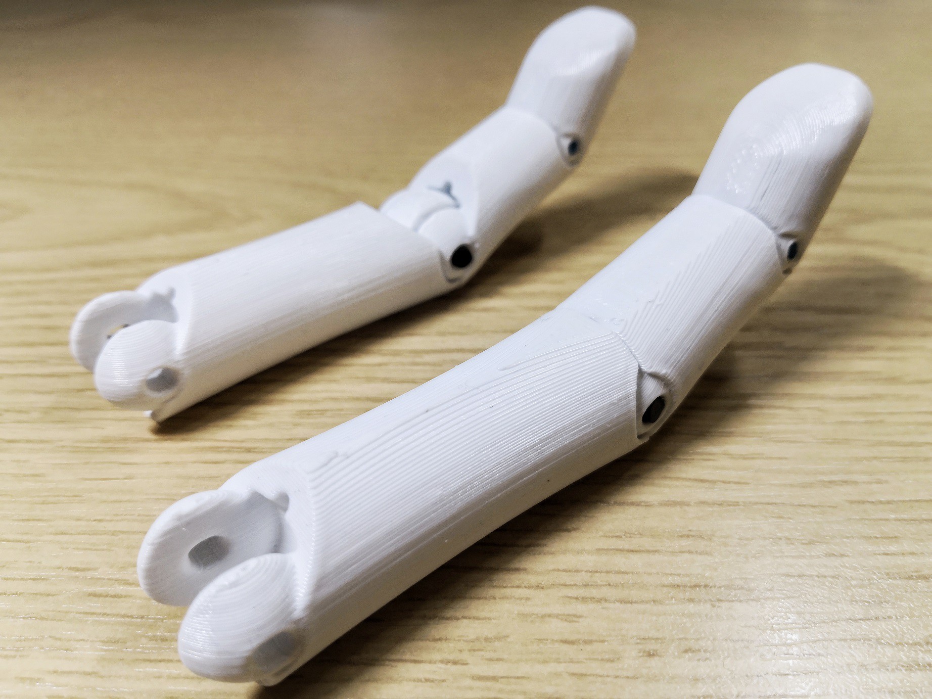
For closing actuation, fingers are actuated through a single cord of 0.5mm to 0.8mm diameter braided fishing line attached using a screw. For opening actuation, fingers are opened using an elastic material attached on the back side. The method of attachment of the elastic material allows for a number of options that available or easily accessible. Elastic cords can be used through tying knots at ends, and elastics can be printed or made through casting, injection moulding or die cutting. Detachable cords also allow for easy replacement or disassembly of fingers.
Fingers can be printed without supports for little to no post processing needed for assembly. Supports may however be required if there isn't enough adequate cooling for overhanging areas. Additionally, TPU grips...


 Andrew Bahls
 TAIBHSE DESIGNS
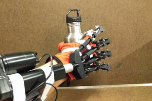
 Chad Paik