| USB |
|---|
| USB connectors are for power only !!!! not for programming !!!! |
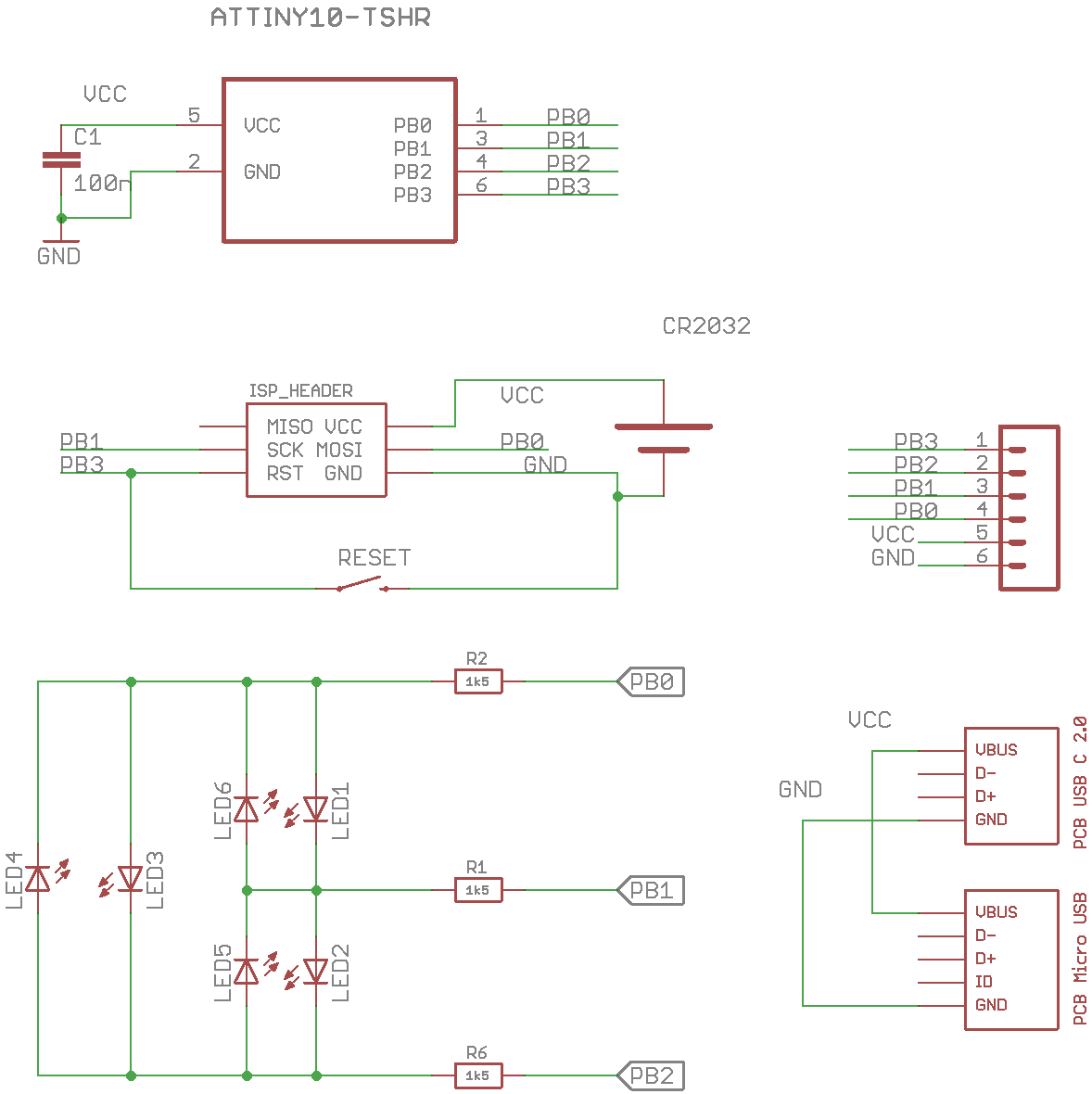
The ATtiny10 is a high-performance, low-power Microchip 8-bit AVR RISC-based microcontroller combines 1KB ISP flash memory, 32B SRAM, four general purpose I/O lines, 16 general purpose working registers, a 16-bit timer/counter with two PWM channels, internal and external interrupts, programmable watchdog timer with internal oscillator, an internal calibrated oscillator, a 4-channel/8-bit A/D converter, and four software selectable power saving modes. The device operates between 1.8-5.5 volts.
Special features
- 6x charlieplexed LED controlled with 3GPIO
- ATtiny10
- Reset buton
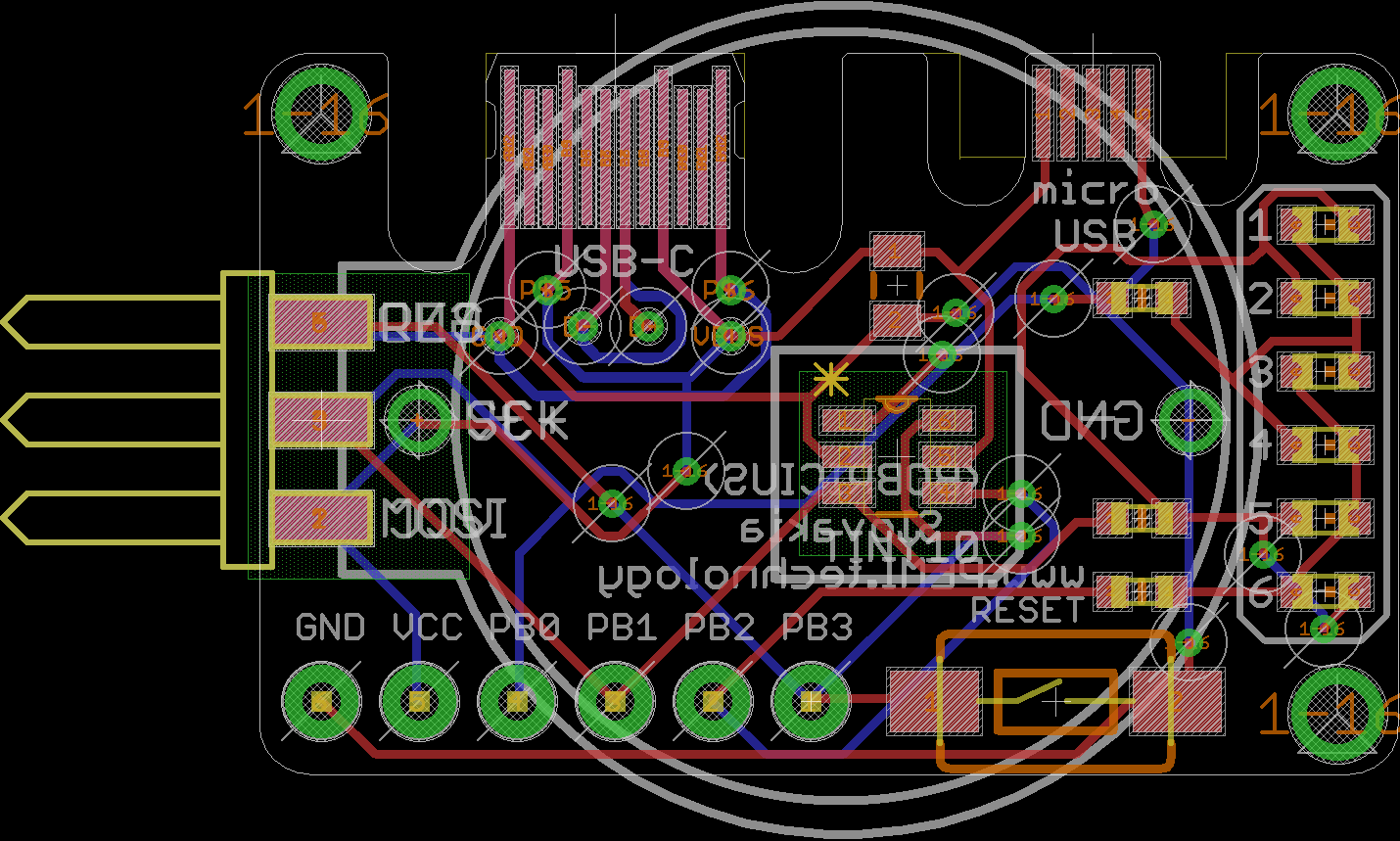
- single row header
- 6pin edge programming header USBasp compatible ISP / TPI (not soldered)
- 0.6mm ENIG GOLD PCB board
POWER options
- from header
- CR2032 (holder not included)
- PCB micro USB
- PCB USB-C
About PCB USB connector
- They are invented with amazing engineer Juan Jesus, he share this shape
https://hackaday.io/project/28516-business-card-gamepad
https://hackaday.io/project/28516-business-card-gamepad
What's not included
- at first install TINY10 core try some sample codes and look for error messages
- time for experiments
- TINY10 core https://github.com/technoblogy/attiny10core
- Read TINY10 core guide http://www.technoblogy.com/show?1YQY
- TPI programmer or USBasp with TPI support ()
- 6pin ISP adapter
What you can try if it's not working
- google search
- TPI is 5V ... switch your USBasp programmer to 5V
- If your USBasp have no TPI support update firmware (you need another USBasp to upload)
- check if AVRDUDE support attiny10
Shipped with preloaded sample flashing code
(KITT efect)
#include <avr/io.h>
#include <stdint.h>

int main (void) {
DDRB = 0b0111;         // Equivalent to pinMode

while (1)
{
led (2,1); //1
led (1,2); //2
led (1,4); //3
led (4,1); //4
led (4,2); //5
led (2,4); //6

led (4,2); //5
led (4,1); //4
led (1,4); //3
led (1,2); //2

}

}

void led (char plus, char minus)
{
 DDRB = 0b0111;         // all input;
 DDRB = plus | minus;
 PORTB = plus;
 PORTB = minus;
  delay (200);
}
void delay (int millis) {
  for (volatile unsigned int i = 34*millis; i>0; i--);
}
 bobricius


 s7a73farm
 icstation
On my own project I had a hard time programming the tiny with anything else in the circuit. Did you have a similar experience?