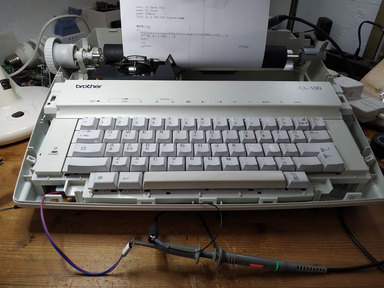
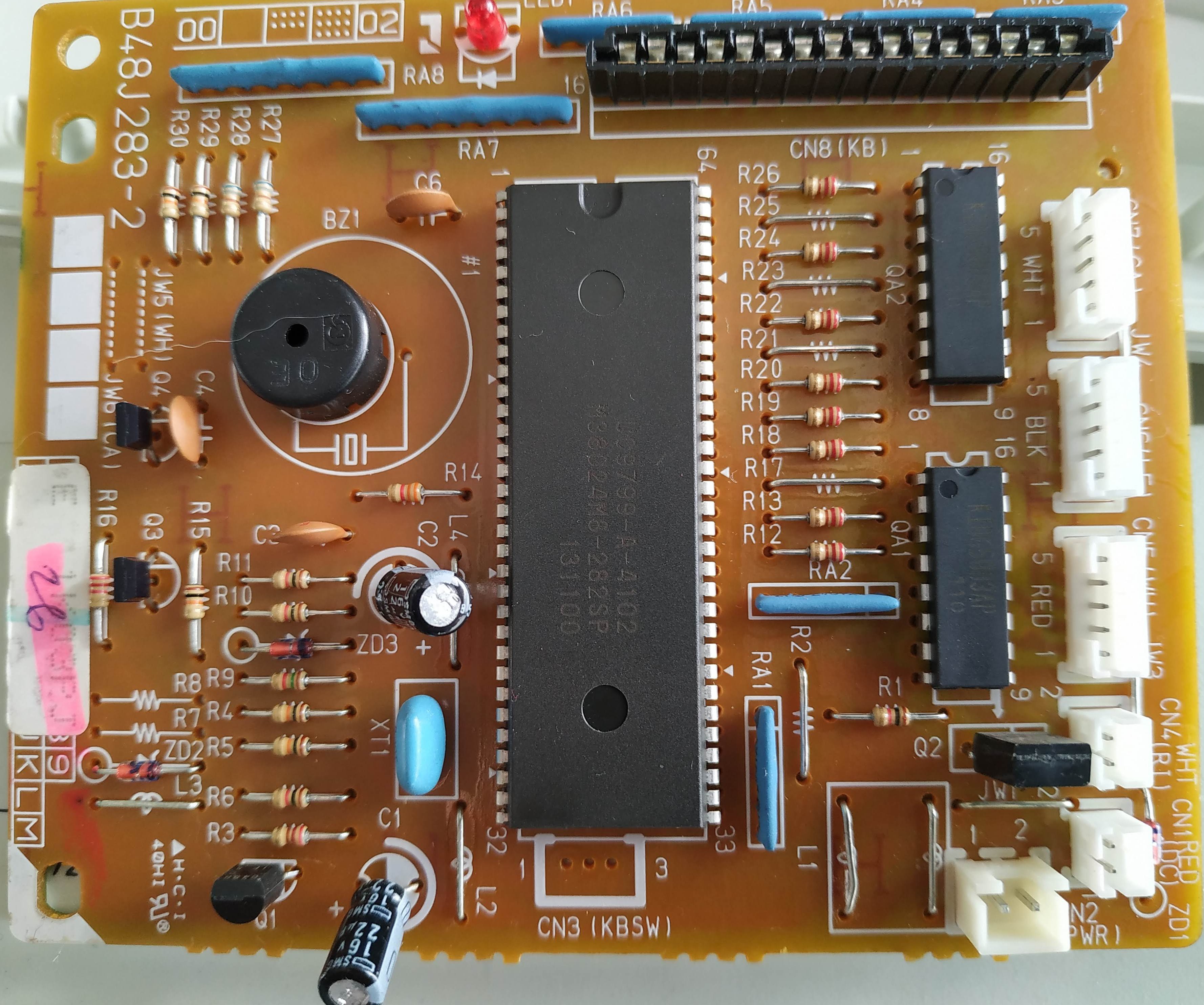
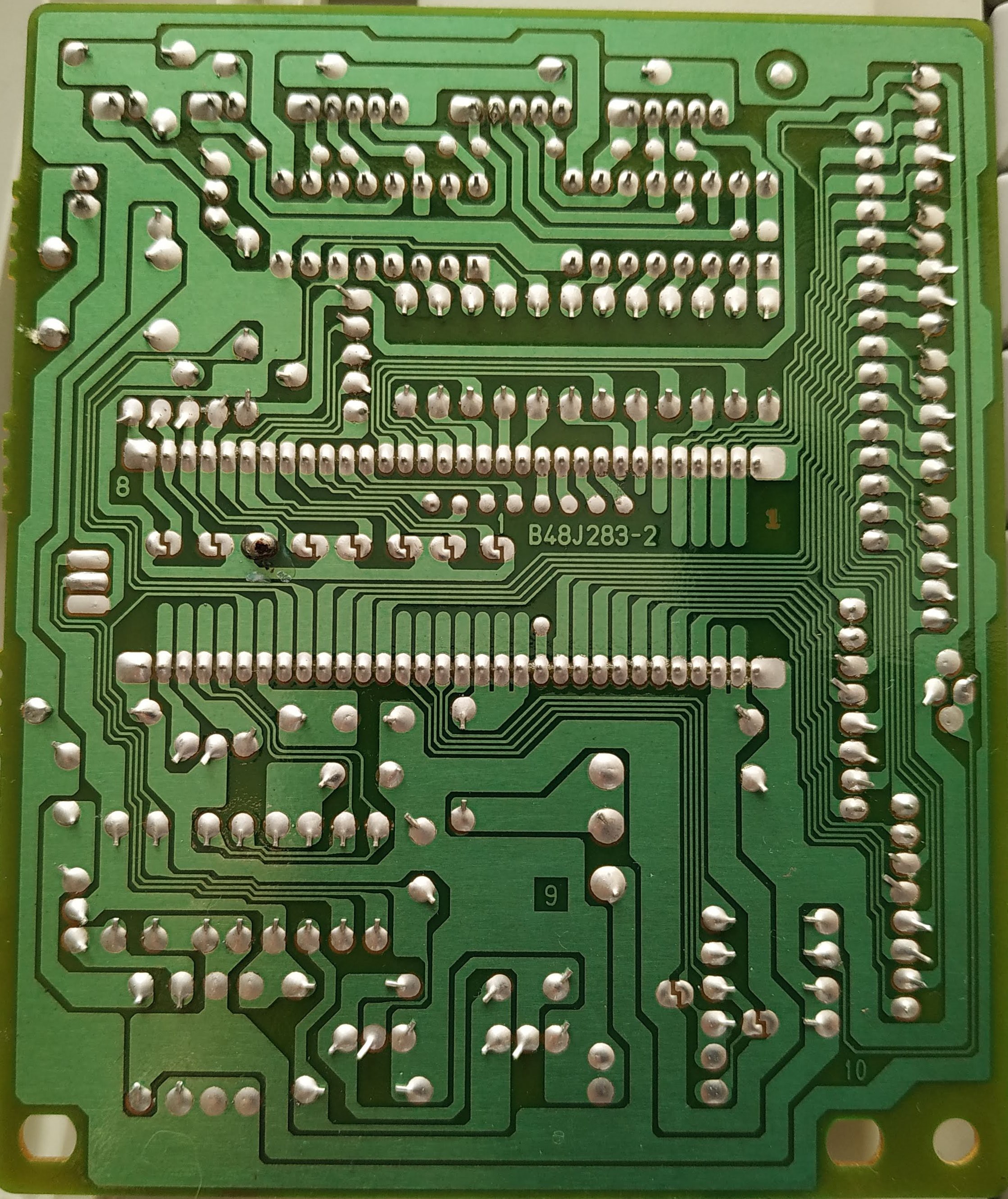
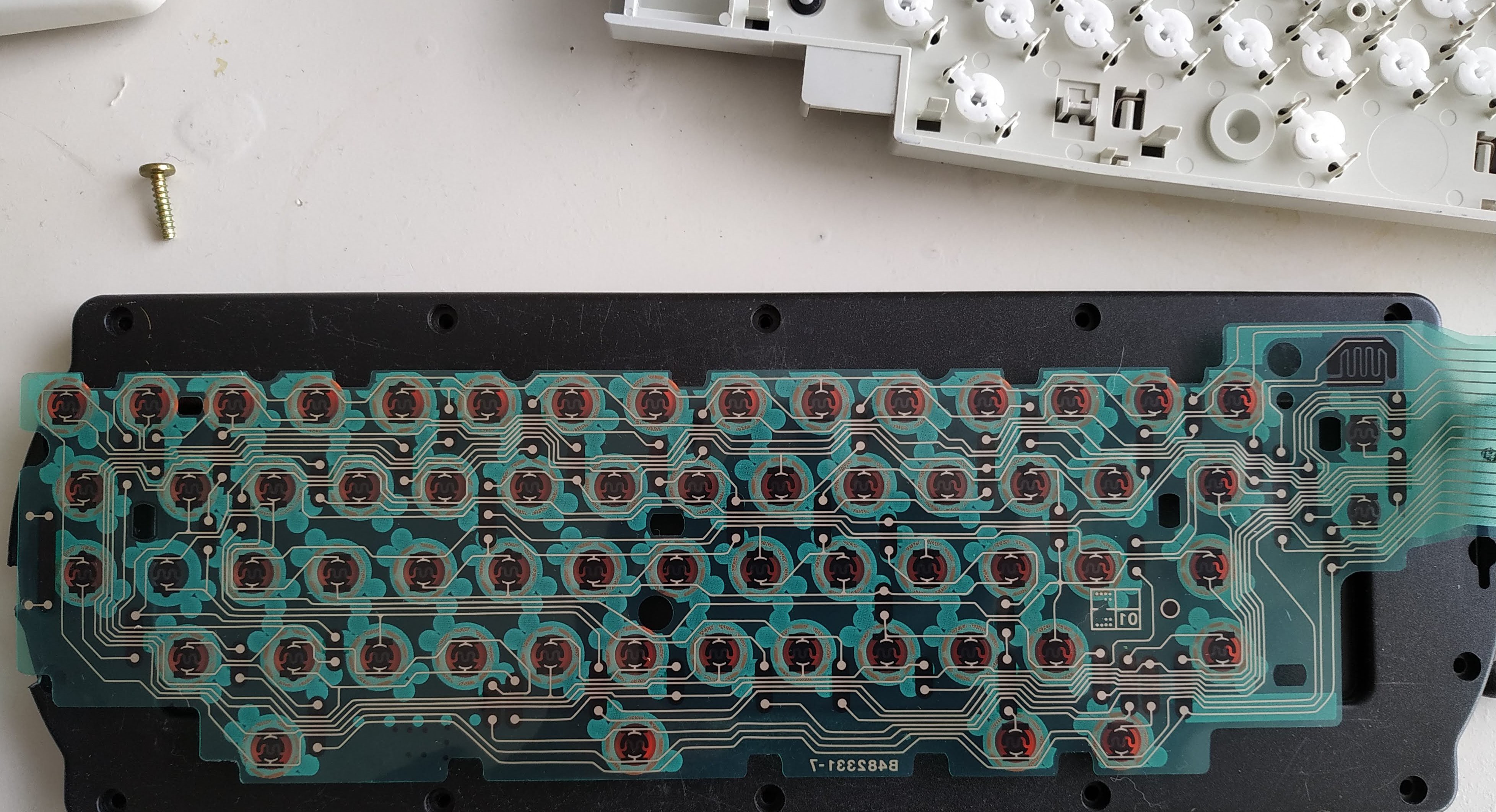
• Progress, and time to put this aside

    Owen10/05/2019 at 21:07 0 comments

    Well, I made good progress over the weekend, 

    First I spent time with al the bits of documentation I have, and the pcb from the typewriter (it's very fine tracked, but single sided, easy to read).

    Then I instrumented the PCB with some probe pins to Serial2, and brought them, 5v and Gnd out and refitted the keyboard.

    Somewhat unsurprisingly I didn't see any signals at all on  either pin, they go low->high at poweron and remain that way.

    Having researched stuff I was totally unsurprised, there are no variants of this typewriter with a serial/centronics output, and this board/processor combo does not appear to support any external (non-debug) comms. 

    Given time constraints I'm going to put this aside now, if it was quick-n-easy I'd have gone further but at this point I'm into interpreting and responding to the 8x8 scan matrix of the keyboard. Quite doable but not on my time budget ;-)

    Something earlier and similar is here; the author of this went further than me and has a arduino sketch that sends keystrokes to Brother typewriter of the same era that appears to have the same keyboard setup.

    http://numist.net/post/2010/project-typewriter.html

    I have some great pictures of the pcb and keyboard track layouts, so I'll upload them up too for reference. 

    I'll stuff all the useful photos in an archive and upload it for reference.

    Note: This is the *back* of the keyboard,the key positions are mirrored.

  • Tracing the PCB

    Owen10/04/2019 at 13:18 0 comments

    Tracing the PCB is relatively easy, it's a single-sided non-smd unit. Quite compact, very fine tracks in places, but very easy to trace too.

    According to the datasheet the M3802 CPU has two serial interfaces built in:

    1. Serial 1
      Pin 20 - RDY
      Pin 21 - CLK
      Pin 22 - TX
      Pin 23 - RX
       This serial can support a UART (no cts/rts needed)
    2. Serial 2
      Pin 16 - RDY
      Pin 17 - CLK
      Pin 18 - OUT 
      Pin 19 - IN
       This serial needs to use cts/rts

    All pins refer to the 64 pin DIP package as used in the AX-100

    Tracing through on the B48J283-2 PCB I see:

    Serial 1

    Pins 20 through 23 go into the 16-wire parallel bus which in turn connects to the keyboard; like all keyboard bus pins they have a resistor array to pull them to VCC. There does not appear to be anything 'special' about them at all. I'd need to do a more detailed trace to determine exactly which kbd lines they go to,

    Serial 2

    Pins 16 and 17 (rdy/sck) go through R27 and R28 (value not yet known) and then connect together and go to the cathode of the 'power' LED on the board (the anode goes to VCC)
    - Look like these pins are used to control the LED, presumably they use two pins to provide sufficient current.

    Pins 18 and 19 (out/in) are pulled to VCC by R29 and R30 (no values yet) , each has an (open) solder jumper to 0V and empty positions for a jumper wire (JW5 and JW6) to 0V too.

    Solder Jumpers

    There are 10 solder jumpers on the copper side of the board, 8 are under the CPU, two are on the Serial2 in/out lines near the JW5/JW6 points on the board. All go (eventually) via a resistor array to VCC and are pulled to ground by the jumper.

    On my board the 6th jumper on the row under the CPU is shorted (counting from the 'top' of the cpu) . All others are open, there are no markings for them on the board.

    The repair manual lists these jumpers along with an optional extra switch connector (CN3, keyboardswitch) and two resistors (R10 and R11) in a matrix for setting the language for the board. I do not have CN3 populated, but R10 and R11 are present. This conflicts with the matrix since in that R10,R11 and CN3 are always present or absent as a set.

    However, having the 6'th jumper on the row of 8 closed corresponds to the GBR.ENGLISH line in the matrix, which is the correct language for the typewriter.

    I believe CN3 is a switch on some international keyboards to switch between between two languages/character sets.

    I've uploaded the relevant bit of the manual to the project files

  • Repair Manual

    Owen10/04/2019 at 08:41 0 comments

    I just managed to google out and download a copy of the repair manual for this. Excellent.

    It does not have a circuit diagram, but it does have a component list for the PCB, and a full list of all the jumpers on it and their functions.  This is great, there are a bunch of solder bridge points on the board, only one of them is connected, I was wondering what they did. Language selection appears to be the main goal.