 Stefano
Building a relay based computer is surely the ultimate retrocomputing experience, and my wish is to try to engineer what could have been the very first electronic computer.
With this build I will also try to teach to my daughter some concepts regarding computers that are difficult to see from an high level perspective, and hope also others will find it useful fun and educational!
The goal of this particular implementation is trying to minimize the number of relays removing all possible redundancies still maintaining all the characteristics of a general purpose modern computer. New optimal designs have been already proposed for ALUs (https://hackaday.io/project/167879-optimized-alus-for-relay-based-computers), and here there is a similar continuation for the rest of the computer.
Less relays means a cheaper project, but also easier and faster to build and less space consuming (never too much)!
Below the "high level" architecture:
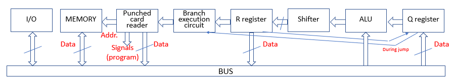
Please note that the 2 registers are called Q and R instead of the usual A and B just to avoid confusion with the ones described in the ALUs that are usually both input ones, while here R is the result register (that contains also the carry flag).
One of the key design differences among many of the current proposals is the utilization of punched tape for the program input. The main reason to opt for this choice is the obvious fitting with the period, but there are many others:
- Possibility to simply easily add more control signals simply adding more "hole columns" if needed
- No need for an external clock, since timing is embedded in the punched signals themselves; and this means less relays
- Easy sub shifting of the individual signal timing, and this means no need of complex clock circuits and more relays
- Possibility to easily regulate overall speed, simply changing the speed of rotation
- Writing directly signals there is no need for decoding logic; this means fewer relays but also faster execution
- Primitive and inexpensive technology available even before the period
- No limit of program length
- No need of PC counter and separate bus (or access logic); this means fewer relays, even though there is the need for circuitry to manage the jump instructions
- Tape program input is faster than manual input (e.g. with switches values stored in RAM) and more elegant and appropriate than EPROM solutions
Surely the fact that there are not already ready modules and a custom build is required is a cons, but the willingness to avoid using more modern technologies is a key factor. Anyway I hope to be able to find an easily buildable solution, and in internet there are already very simple ones to take inspiration from.
For the branch execution management circuit I will fully reuse the ALU (that has an arrangement thought also for this purpose), saving dedicated relays. The control will happen with some parallel dedicated signal support (saving firmware logic and more relays).
Again trying not to use silicon based solutions, regarding RAM I'm working on an original design based on capacitors. The direct memory access (with addresses coming directly from the program) reduce even more the relay count without really affecting programming potential.
Output will be visible on registry relays lamps. Punching cards would be very nice, but this might be a very last addition since the device will not be so simple to be built at home. Instead there will be probably the interface with a parallel printing device. An audible buzzer is completing the capabilities.
On the input side there are a set of switches addressed as the memory and a button to restart execution after halt instruction. More inputs can be read halting the execution between them.
The PC will support an «high level» instructions compiler, but can be also microprogrammed in order to have full control and optimization possibilities.
The supported instructions are by categories:
"data moving"
- Q = R
- Q = constant
- Q = Memory[address]
- R = Q
- R = constant
- R = Memory[address]
- Memory[address] = constant
- Memory[address] = R
"arithmetical and logical operations"
- R = Q + constant
- R = Q + Memory[address]
- R = Q + Memory[address] + 1 (carry, e.g. for 2's complement subtractions)
- R = Q And|Or|Xor|Xnor|Nand|Nor|WhateverBitwiseOperation constant
- R = Q And|Or|Xor|Xnor|Nand|Nor|WhateverBitwiseOperation Memory[address]
- R = Shift Left Q (arithmetic)
- R = Shift Right ALU result (this can be done togheter with all others ALU functions previously mentioned)
"program control"
- Halt (wait until "resume" button is pressed)
- Jump Q «jump labels» forward or backward (in 2’s complement notation)
- Jump comditionally Q labels if Carry, or if Sign, or if Zero (all condition apply to R and are optionally selectable and joinable)
"input/output"
- Q = User Input
- Print Q on external parallel printer (the electromechanical one to be designed! :))
- Ring the bell
Note: the design is easily extendable to word size of whatever multiple of 4 bits (with no implications on signal speed since there is no accumulating delay depending on word lenght). For the actual implementation I decided to go with 8 bit, adding few relays to the simpler 4bit one but being on a more standard byte data format.
More details of the various parts and build advancement in the project logs:
1. Let's start: https://hackaday.io/project/167895/log/170115-lets-start
2. Quality checks: https://hackaday.io/project/167895/log/170345-quality-check
3. Planning the layout: https://hackaday.io/project/167895/log/170367-planning-the-layout
4. Click clack: https://hackaday.io/project/167895/log/170685-click-clack
5. Slow but steady progresses: https://hackaday.io/project/167895/log/185293-slow-but-steady-progresses
6. Main unit completed: https://hackaday.io/project/167895/log/186817-main-unit-completed
7. Memory module: https://hackaday.io/project/167895-super-micro-relay-computer/log/186827-memory-design
.