 Stefano
With the usual slow but steady speed finally the main module wiring has been completed!
And all functionalities tested worked as expected! There were just a few wiring errors but all of them cought during build time (one wire during the initial two bits test of the ALU, while all the others during immediate recheck of the step work done).
Below the result:

This is the main unit, missing "just" the random access memory module and the punched tape reader to be a complete system.
This unit contains: 2 registries, a complete 8 bits ALU with carry bit in and out (able to perform all 16 logic operations, additions, and shifts in both directions), all the bus access interfaces required and the "halt" and "jump" management circuits to control the code flow.
Below some details regarding the implemented halt and branching management circuits (the one for ALU and Q register were detailed also here https://hackaday.io/project/167879-optimized-alus-for-relay-based-computers/log/186329-super-micro-relay-computer-cabling).
BRANCH MANAGEMENT CIRCUIT
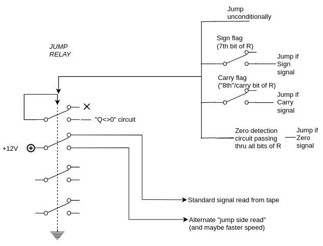
The branch execution circuit is activated when one of the signal of jump "go through" the correspondent condition and activates the jump relay.
Before the jump, Q should be set with the negative value of the numbers of labels to skip, and the circuit stops when Q is zero.
During the jump execution the current is removed from "normal" tape signals and given to a section of tape dedicated to jump instruction where at each label there is:
1. load R with Q+1
2. load Q from R
When Q will become 0 the signal will automatically go back to the standard instructions side of the tape and instructions signals might also be written "longer" in order to be able to execute at faster tape rotor speed.
Notes
1. jump side signals and standard signals cannot be put on the same "line" since even if not active they might interfere in terms of connections.
2. since the number of labels to skip is parametric call/return can be easily implemented (one memory location can be used for the return address) and also indirect jumps are supported by design
3. backward jumps can be transformed into forward jumps if the paper tape is connected in a loop (buth the only forward mechanics should be much easier)
4. to implement a real backward jump another relay should be required to invert the engine poles and to select a second side track that will do Q-1 instead of Q+1 (and with instructions in reverse order since the tape will move backward); this additional switch can be controlled by the higher bit of Q so effectively allowing a -127 to +127 range (instead of the current 1 to 255 labels)
HALT CIRCUIT
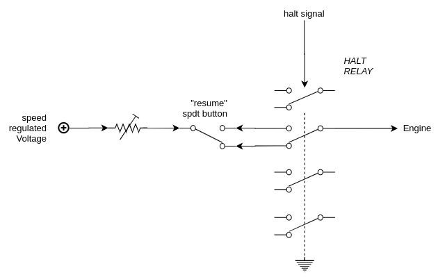
The halt circuitry is optional but very useful since apart at the end of the program can be used for example to input multiple values (or parts of a single larger input) with a cycle:
1. halt (to allow input switches reconfiguration)
2. move switches value to proper memory location
3. go to 1 for the number of times required
The configuration avoids that a single keypress skips more than a single halt since the press will advance tape until the halt signal on the tape will stop and to continue the button have to be released.
Discussions
Become a Hackaday.io Member
Create an account to leave a comment. Already have an account? Log In.
yes, much more clear. now, about subroutines and return addresses; how will you acomplish that? Thankyou for so patiently answering my questions. I am more excited by your jump plans! Please have a good answer for subroutine call/return. hack on!
Are you sure? yes | no
The indirect jumps are the key here: in order to implement the call/return you need to use one location of the memory to store the return address before performing the call (each place where you will call the subroutine have a different return address). At the end of its execution the subroutine simply take this fixed location and jumps back!
With a larger memory (let's say 256 bytes) also a stack can be implemented, using one memory location to address the current stack top, and so also recursion can be possible within this architecture! :)
Are you sure? yes | no
but i thought you didn't have a pc or address bus!
Are you sure? yes | no
so i think i understand what your doing with the jumps. Let me tell you what I imagine... people are standing beside the tape reader, and when they should ( how do they know?) they will quickly pull the tape past the reader untill the targeted label is read then they go back to pulling the tape slowly past the reader. Is that how you imagine it working? Theres the issue of the people pulling the wrong way, forward when they should go back, and the oposite mistake. Preventing and recovering from these mistakes isn't clear to me. Can you help? Also why the concern with jumps being backward or not (your second note) and what are you thinking with your third note? help.
Are you sure? yes | no
No people involved, please! :)
The punched tape is rolling without stops, driven by a small electric engine.
Under the paper there is an electric sheet with power and the pins are conductive and attached each one to a different signal, so that the signal will receive voltage power when there is an hole in the paper (here you can find a poor-man version of that https://maker.pro/storage/928c735/928c7352797eefc8bdaffd796b68a277.jpeg done with clips). There are also other designs but mechanically this seems to me the easier.
To manage jumps simply there are two adjacent sides of the tape (the conductive base is split in two): one with the signals for "normal program", the other with the signals that will just elaborate a "Q=Q+1" each time there is a label at that point. And even if they are on the same tape, just one of this two sides gets the voltage to execute instructions.
Normally is the "normal" side that gets the power for the signals and so the instructions written there are executed. When "jump mode" triggers, the voltage is removed from the normal side (meaning instructions will not be executed even if holes are passing on signal pins) and instead the "label side" get the power, simply incrementing Q each label is encountering. When Q becames zero (means the proper label has been reached) the jump stops and the program gets again the voltage for the instructions. In all this the paper simply continues to move normally. All jumps are relative, and in order to perform the jump, Q should be simply preloaded with the negative value of labels to skip.
All modern conditions are implemented for the activation of the jump management circuit: carry, sign, zero and of course the unconditional one.
Note that for now I implemented just the forward jumps, with the idea to implement backward ones with a closed loop tape (so with a forward jump past the beginning). Implementing also backward jumps can be done with the same relays and motor, but would require sligtly more complicated mechanical setup (with the ability for the paper to go backward) and other signals on the tape.
Hope is more clear.
Are you sure? yes | no
sorry my reply ended up at the top of the thread... not down here..
Are you sure? yes | no