 DIY GUY Chris
Hey guys! I Hope you already enjoyed my previous project "Arduino LIXIE Clock" and you are ready for a new one, as usual I made this tutorial to guide you step by step while making this kind of super amazing low cost electronic projects which is the "Arduino Heart pulse device".
During the making of this project, we tried to make sure that this project will be the best guide for you in order to help you if you want to make your own ECG, so we hope that this project contain the needed documents.
This project is so handy to make specially after getting the customized PCB that we’ve ordered from JLCPCB to improve the appearance of our electronic device and also there is enough documents and codes in this guide to allow you create your Arduino Heart pulse display easily. We've made this project in just 3 days only, just two days to get all the needed parts and finish the hardware making and the assemble, then we have prepared the code to suit our project and start the testing and the adjustment.
What you will learn from this instructable:
- Making the right hardware selection for your project depending on its functionalities.
- Understand the heart pulse sensor technology.
- Prepare the circuit diagram to connect all the choosen components.
- Assemble all the project parts (device box and electronic assembly)..
- Start your own Heart pulse device.
Step 1: How the Heart Pulse Sensor Works!
As defined on Wikipedia "Electrocardiography is the process of producing an electrocardiogram (ECG or EKG[a]), a recording – a graph of voltage versus time – of the electrical activity of the heart[4] using electrodes placed on the skin. These electrodes detect the small electrical changes that are a consequence of cardiac muscle depolarization followed by repolarization during each cardiac cycle (heartbeat)."
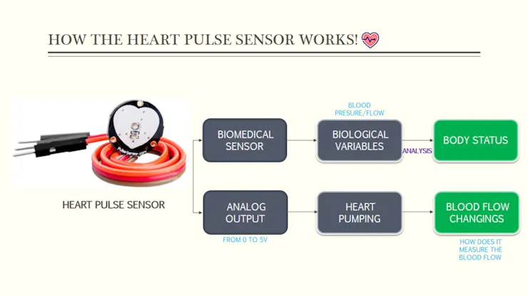
In our case , we are not using electrodes but IR sensor, a heart pulse sensor is a biomedical sensor which
means that it uses some biological and physiological variables to indicates the status of the body.
Talking about variables, our sensor has an analog output which goes from 0V to 5V and this output indicates how much blood flow/pressure the heart is about to pump, but how does this sensor measure these blood flow changings!
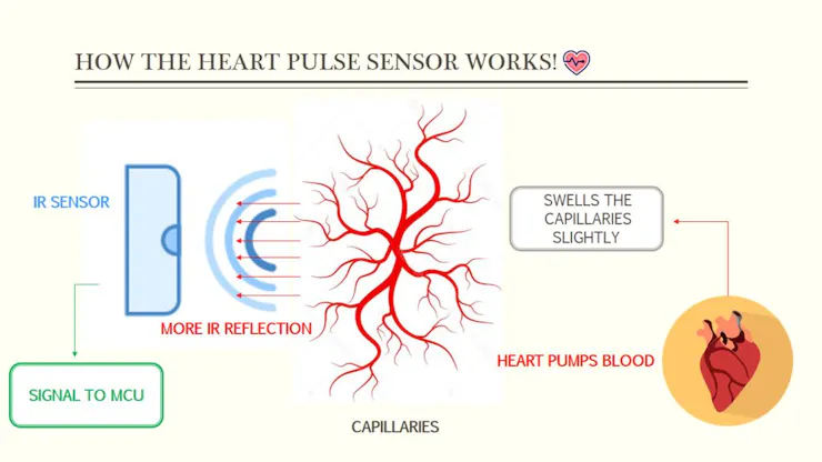
The sensor uses an Infra-Red signal from an IR-Diode projected onto your skin. Just underneath your skin there are capillaries carrying blood. Every time your heart pumps there is a small increase in blood flow/pressure. This swells the capillaries slightly, and just then this slightly more filled capillaries reflect more infra-red. The Infra-detector on the device senses the different reflected IR levels and amplifies the measured signal and convert it into an interpretable voltage signal which could be sent to any microcontroller like the Arduino MCU.
Step 2: CAD and Hardware Parts
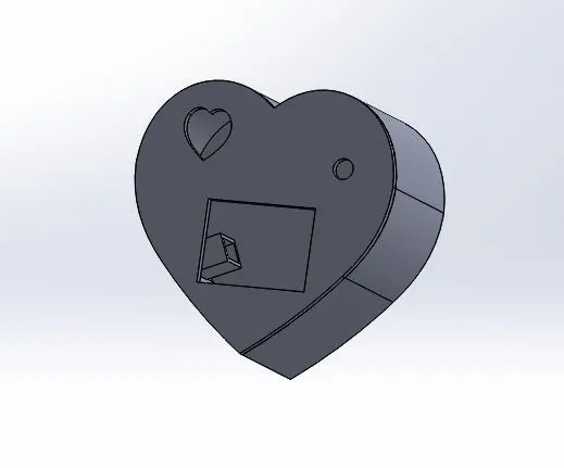
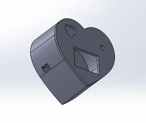
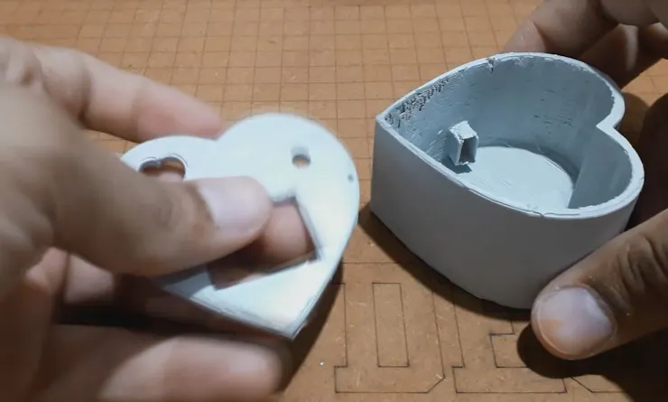

Starting with the 3D printed box parts, I made the above design using solidworks software and you can get the STL files from the download link, this design is 100% recommended to help you making your device since it fits the exact placement for the sensor and the OLED display.
After preparing the design I have got my parts very well manufactured and ready for the action. and as you can see in the last photo we prepared the Power connector placement on the box side.
Step 3: Circuit Diagram
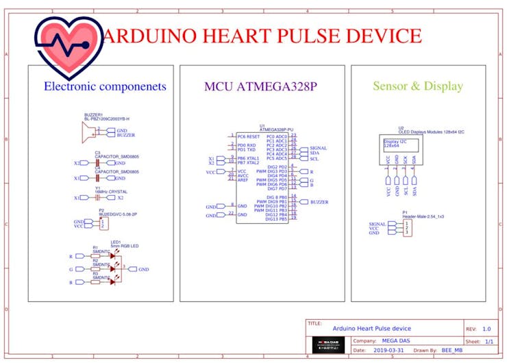
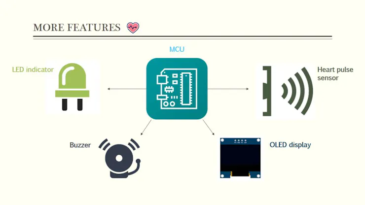
Moving to the electronics, I have created this circuit diagram that includes all the necessary parts required for this project.I am connecting the heart pulse sensor to my ATMega328P MCU and I display the voltage signal received from the sensor through an OLED display, the plot will show the voltage segnal evolution on by time and I use also a buzzer to mark each heart beat, an RGB LED is also used in this project to indicate the BPM status so when the BPM is too low "less than 60 BOM" the LED turns Yellow, when the BPM...
Read more »
Hello, I noticed in your video that the OLED pin order of the PCB is GND, VCC, SCK, SDA, and the physical product is also in this order. But the order in the Gerber file you provided is VCC, GND, SCK, SDA. In my project, OLED and PCB need to be connected using pin header and female
header connections instead of wires, so can you please upload the corrected Gerber file?