 DIY GUY Chris
Hey guys! I Hope you already enjoyed my previous project "Arduino LIXIE Clock" and you are ready for a new one, as usual I made this tutorial to guide you step by step while making this kind of super amazing low cost electronic projects which is the "Arduino Heart pulse device".
During the making of this project, we tried to make sure that this project will be the best guide for you in order to help you if you want to make your own ECG, so we hope that this project contain the needed documents.
This project is so handy to make specially after getting the customized PCB that we’ve ordered from JLCPCB to improve the appearance of our electronic device and also there is enough documents and codes in this guide to allow you create your Arduino Heart pulse display easily. We've made this project in just 3 days only, just two days to get all the needed parts and finish the hardware making and the assemble, then we have prepared the code to suit our project and start the testing and the adjustment.
What you will learn from this instructable:
- Making the right hardware selection for your project depending on its functionalities.
- Understand the heart pulse sensor technology.
- Prepare the circuit diagram to connect all the choosen components.
- Assemble all the project parts (device box and electronic assembly)..
- Start your own Heart pulse device.
Step 1: How the Heart Pulse Sensor Works!
As defined on Wikipedia "Electrocardiography is the process of producing an electrocardiogram (ECG or EKG[a]), a recording – a graph of voltage versus time – of the electrical activity of the heart[4] using electrodes placed on the skin. These electrodes detect the small electrical changes that are a consequence of cardiac muscle depolarization followed by repolarization during each cardiac cycle (heartbeat)."
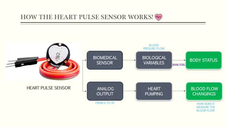
In our case , we are not using electrodes but IR sensor, a heart pulse sensor is a biomedical sensor which
means that it uses some biological and physiological variables to indicates the status of the body.
Talking about variables, our sensor has an analog output which goes from 0V to 5V and this output indicates how much blood flow/pressure the heart is about to pump, but how does this sensor measure these blood flow changings!
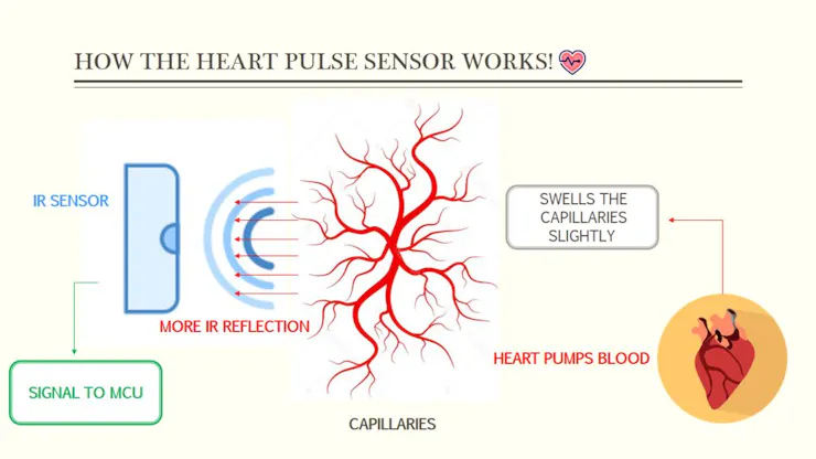
The sensor uses an Infra-Red signal from an IR-Diode projected onto your skin. Just underneath your skin there are capillaries carrying blood. Every time your heart pumps there is a small increase in blood flow/pressure. This swells the capillaries slightly, and just then this slightly more filled capillaries reflect more infra-red. The Infra-detector on the device senses the different reflected IR levels and amplifies the measured signal and convert it into an interpretable voltage signal which could be sent to any microcontroller like the Arduino MCU.
Step 2: CAD and Hardware Parts
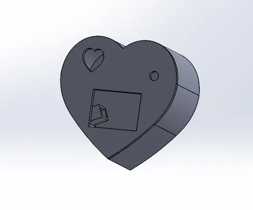
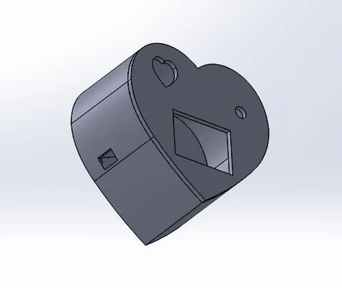

Starting with the 3D printed box parts, I made the above design using solidworks software and you can get the STL files from the download link, this design is 100% recommended to help you making your device since it fits the exact placement for the sensor and the OLED display.
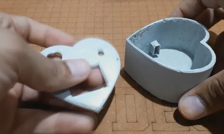
After preparing the design I have got my parts very well manufactured and ready for the action. and as you can see in the last photo we prepared the Power connector placement on the box side.
Step 3: Circuit Diagram
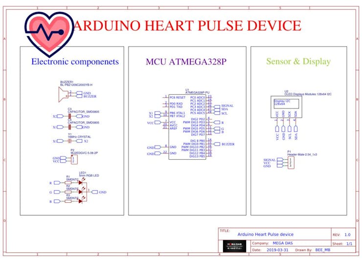
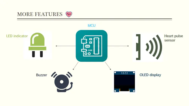
Moving to the electronics, I have created this circuit diagram that includes all the necessary parts required for this project.I am connecting the heart pulse sensor to my ATMega328P MCU and I display the voltage signal received from the sensor through an OLED display, the plot will show the voltage segnal evolution on by time and I use also a buzzer to mark each heart beat, an RGB LED is also used in this project to indicate the BPM status so when the BPM is too low "less than 60 BOM" the LED turns Yellow, when the BPM is OK the LED turns green and when the BPM is too high the LED turns red.
Step 4: PCB Making


About JLCPCB
JLCPCB (Shenzhen JIALICHUANG Electronic Technology Development Co., Ltd.), is the largest PCB prototype enterprise in China and a high-tech manufacturer specializing in quick PCB prototype and small-batch PCB production. With over 10 years of experience in PCB manufacturing, JLCPCB has more than 200,000 customers at home and abroad, with over 8,000 online orders of PCB prototyping and small quantity PCB production per day. The annual production capacity is 200,000 sq.m. for various of 1-layer, 2-layer or multi-layer PCBs. JLC is a professional PCB manufacturer featured of large scale, well equipment, strict management and superior quality.
Talking electronics
After making the circuit diagram I transformed it into a customized PCB design and all what I need now is to produce my PCB, for sure I moved to JLCPCB the best PCB supplier in order to get the best PCB manufacturing service, after some simple clicks I have uploaded the appropriate GERBER files of my design and I set some parameters like the PCB thickness color and quantity, and this time we will use the red color to suits the heart shape design of our PCB; then at least you need to pay just 2 Dollars to get the PCB after four days only, what I have noticed about JLCPCB this time is the "out of charge PCB color" it means you will pay only 2 USD for any PCB color you choose.
Related download files
As you can see in the pictures above the PCB is very well manufactured and I’ve got the same PCB design that we’ve made for our main board and all the labels,logos are there to guide me during the soldering steps. You can also download the Gerber file for this circuit from the download link below in the case you want to place an order for the same circuit design.
Step 5: Ingredients

Before start soldering the electronic parts let’s review the components list for our project so we will need:
★☆★ The necessary components ★☆★
- The PCB that we order from JLCPCB - Arduino Uno : https://amzn.to/2Oqa6uO
- 330Ohm resistors : https://amzn.to/2OtRGJU
- 16 MHz quartz oscillator : https://amzn.to/2OtRGJU
- The heartPulse sensor : https://amzn.to/2OtRGJU
- Buzzer : https://amzn.to/2OtRGJU
- OLED display : https://amzn.to/2OtRGJU
- RGB LED : https://amzn.to/2OtRGJU
Step 6: Electronic Assembly


Now everything is ready so let’s start soldering our electronic components to the PCB and to do so we need a soldering iron and a solder core wire and a SMD rework station for SMD components.
Safety first
Soldering Iron
Never touch the element of the soldering iron....400°C!
Hold wires to be heated with tweezers or clamps.
Always return the soldering iron to its stand when not in use.
Never put it down on the workbench.
Turn unit off and unplug when not in use.
As you can see, using this PCB is so easy due to its very high quality making and without forgetting the labels that will guide you guys while soldering each component because you will find on the top silk layer a label of each component indicating its placement on the board and this way you will be 100% sure that you will not make any soldering mistakes. I’ve soldered each component to its placement and you can use both sides of the PCB to solder your electronic components.
Step 7: Software Part & Test


All what we need now is the software, I have made this Arduino code for you guys and you can have it for free from the link down below, the code is very well commented so you can understand it and adjust it for your own needs, we need the Arduino Uno board to upload the code into our ATmega328 MCU then we take the MCU and we place it in its socket on the board.
We need an external 5v power adaptor to turn ON the device and here we are, as you see guys the device display the Beats per minute and it displays the heart pulses graph plotted on the OLED display without forgetting this RGB LED that indicates the body status too.
This project is so easy to make and an amazing one specially with the OLED Display which could be your best choice to start the biomedical gadgets making but still some other improvements to perform in order to make it much more butter, that’s why I will be waiting for your suggestions to improve it.