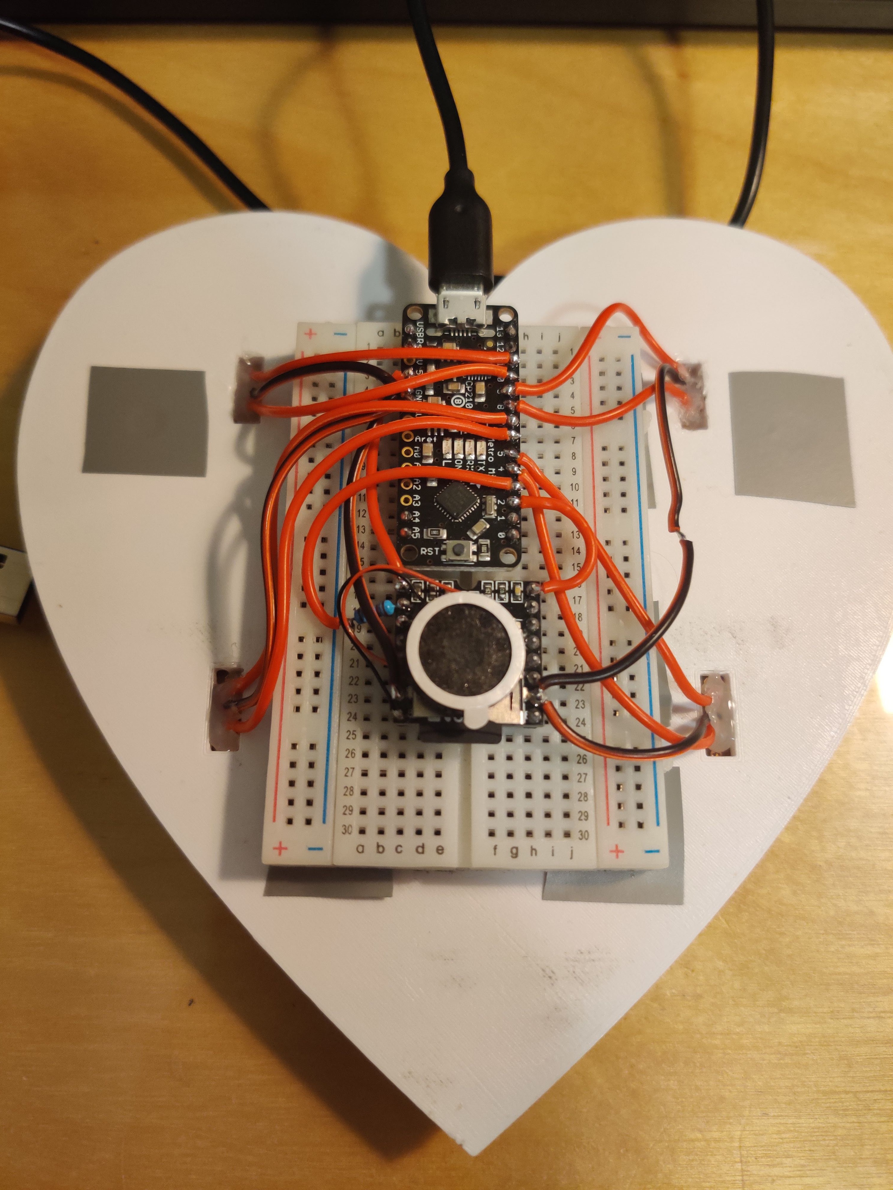
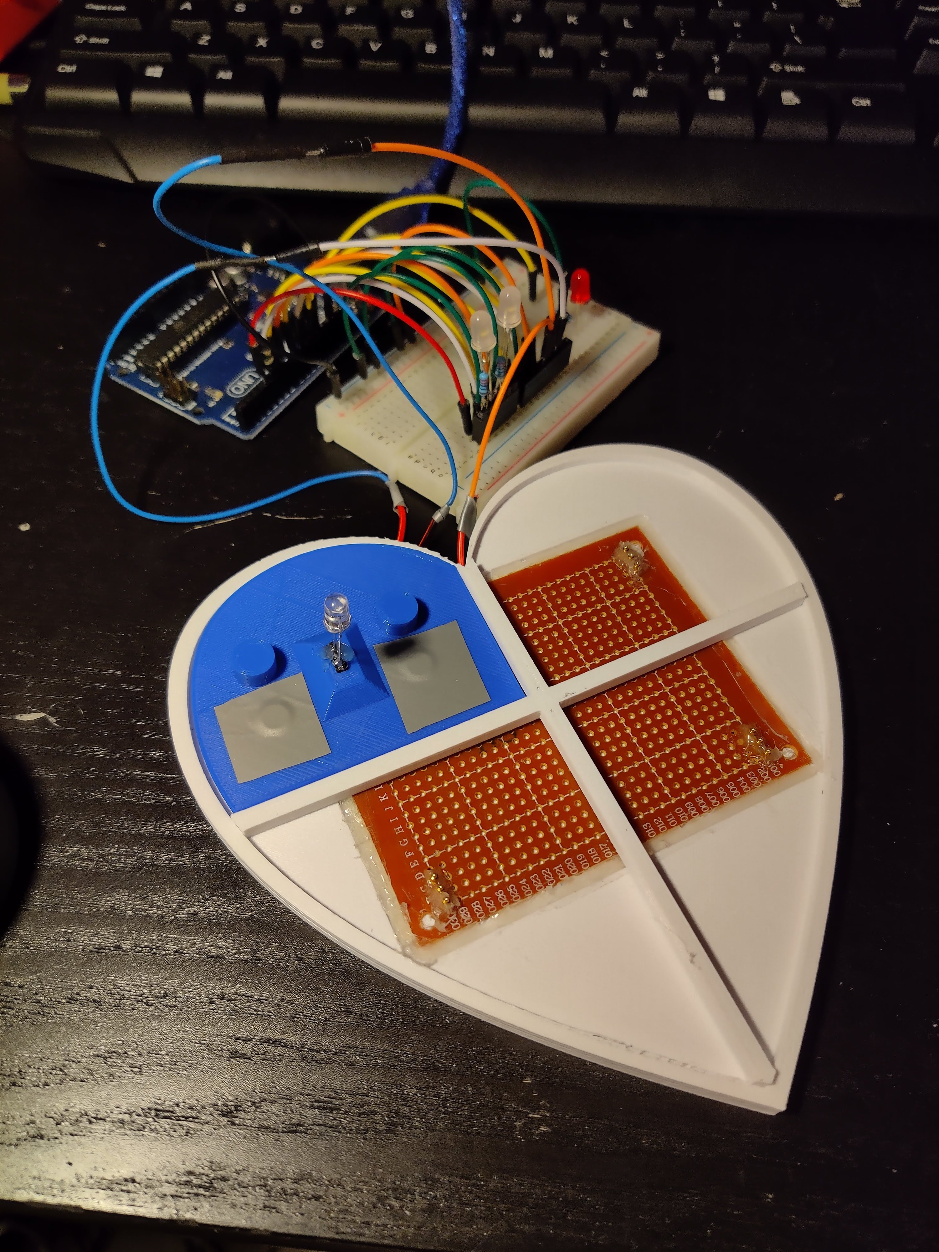
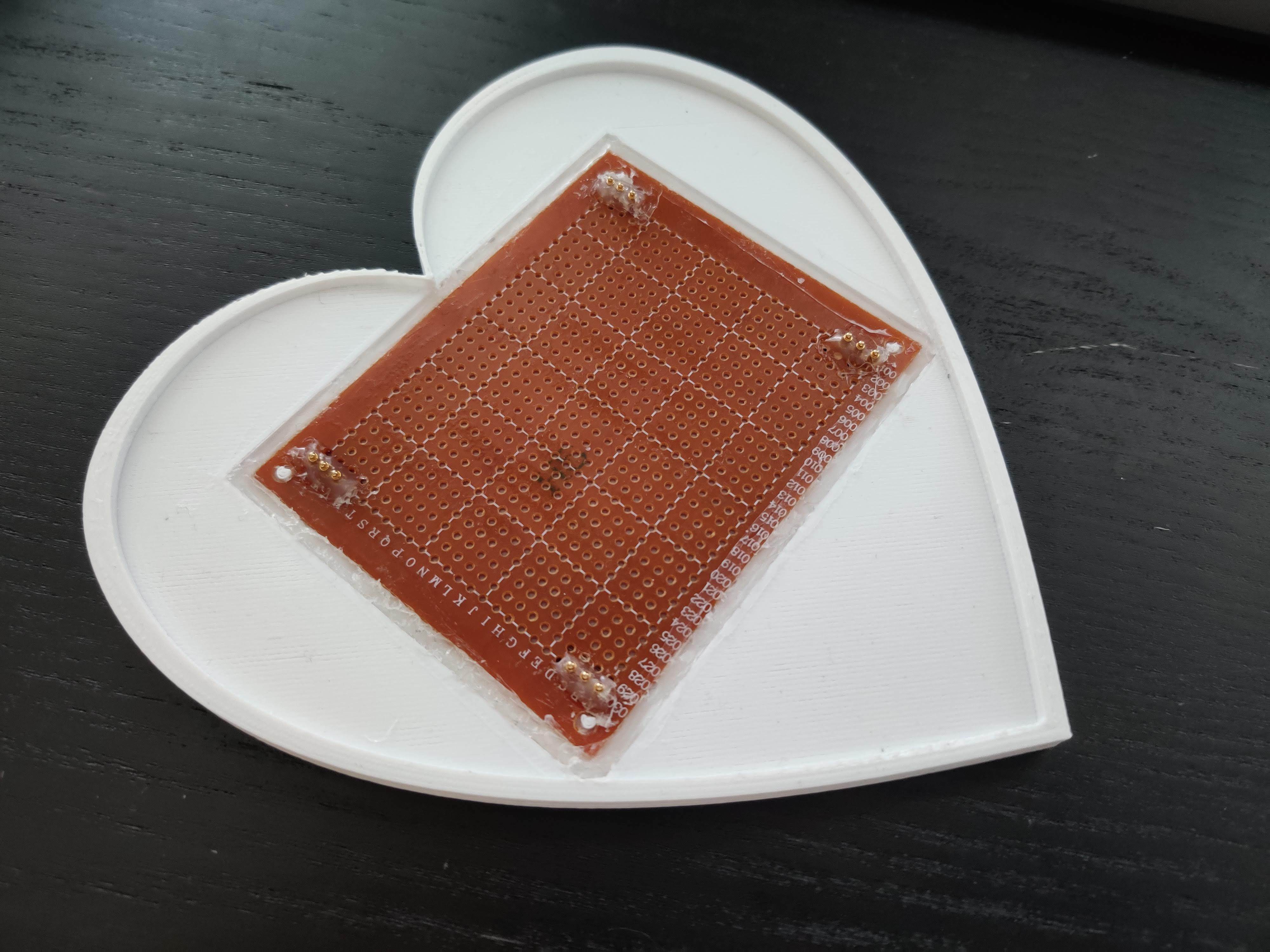
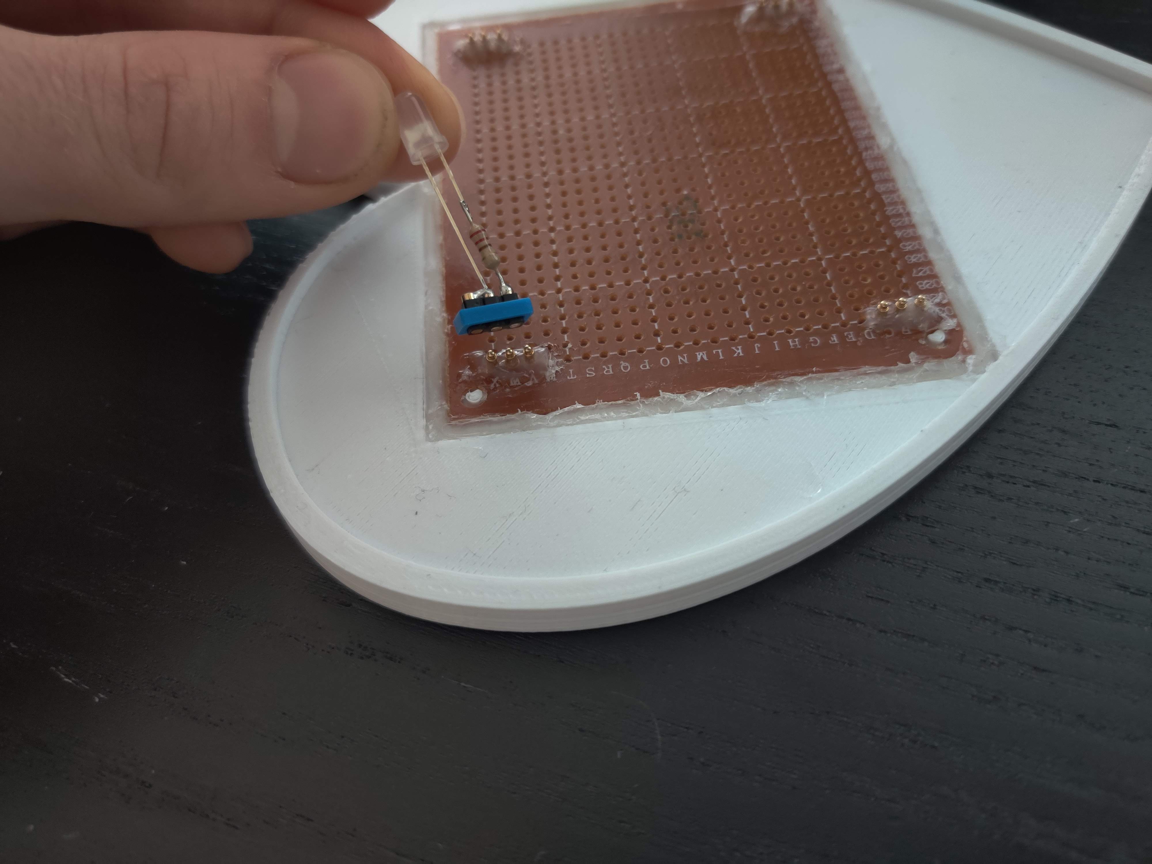
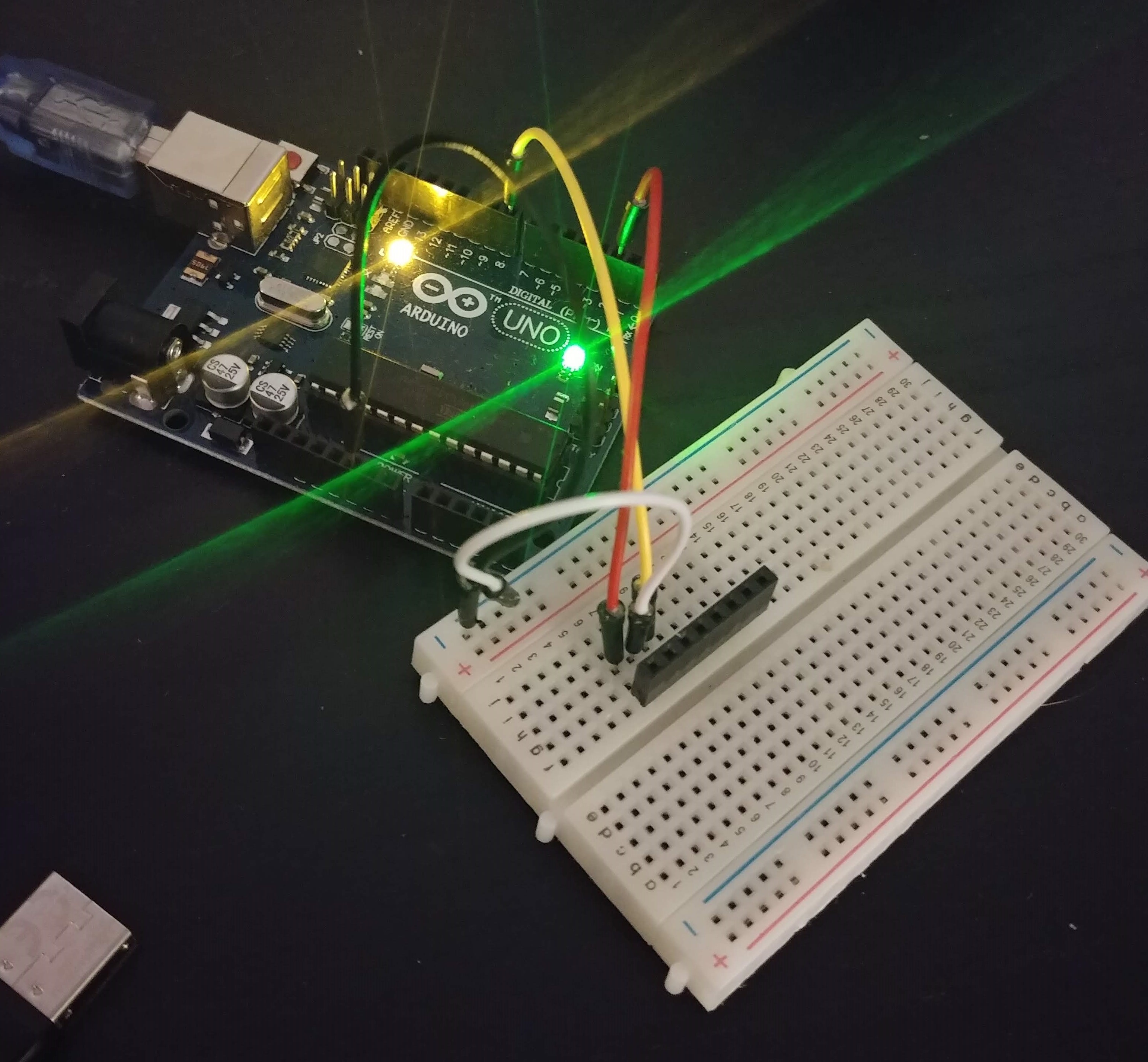
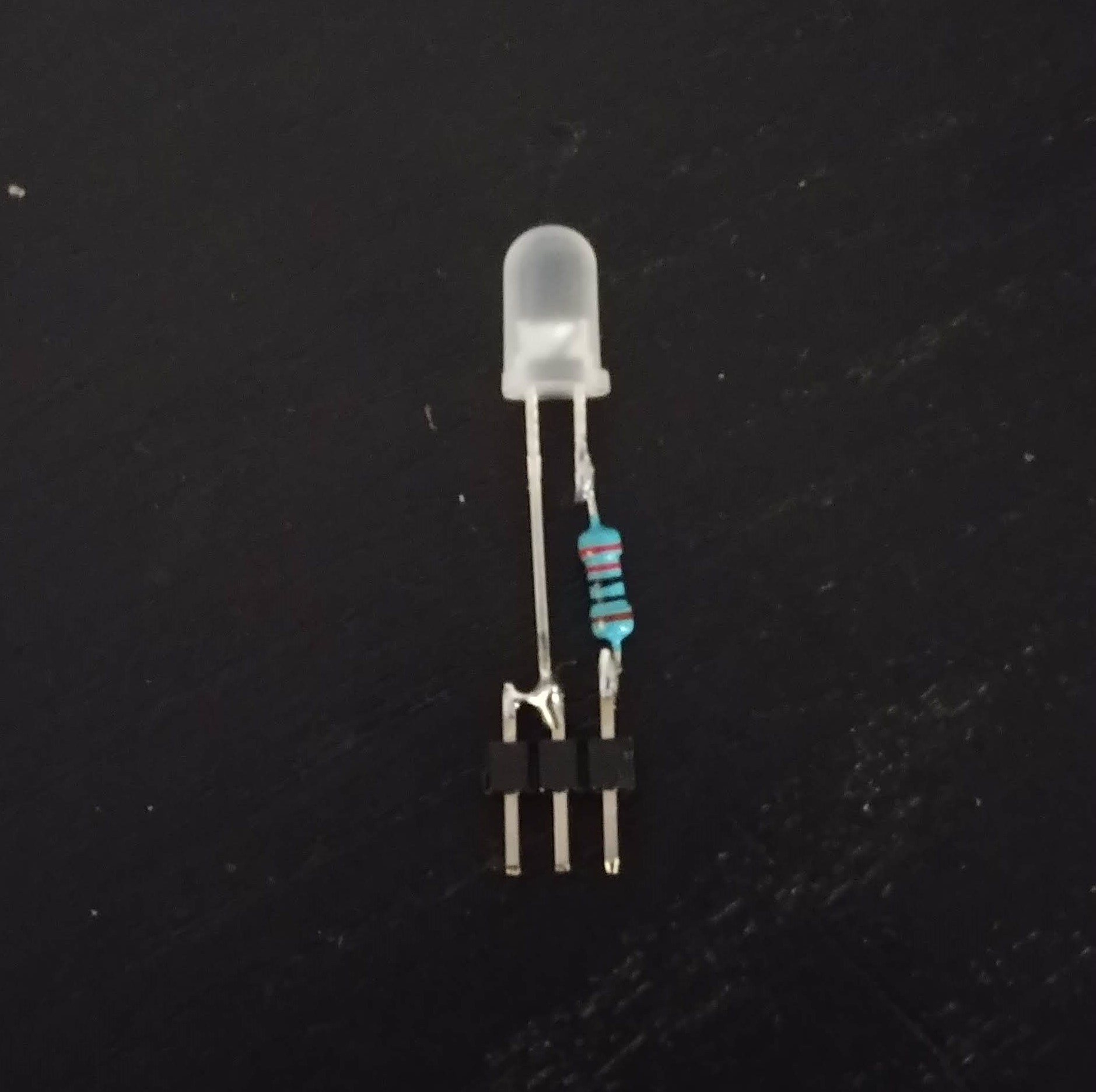
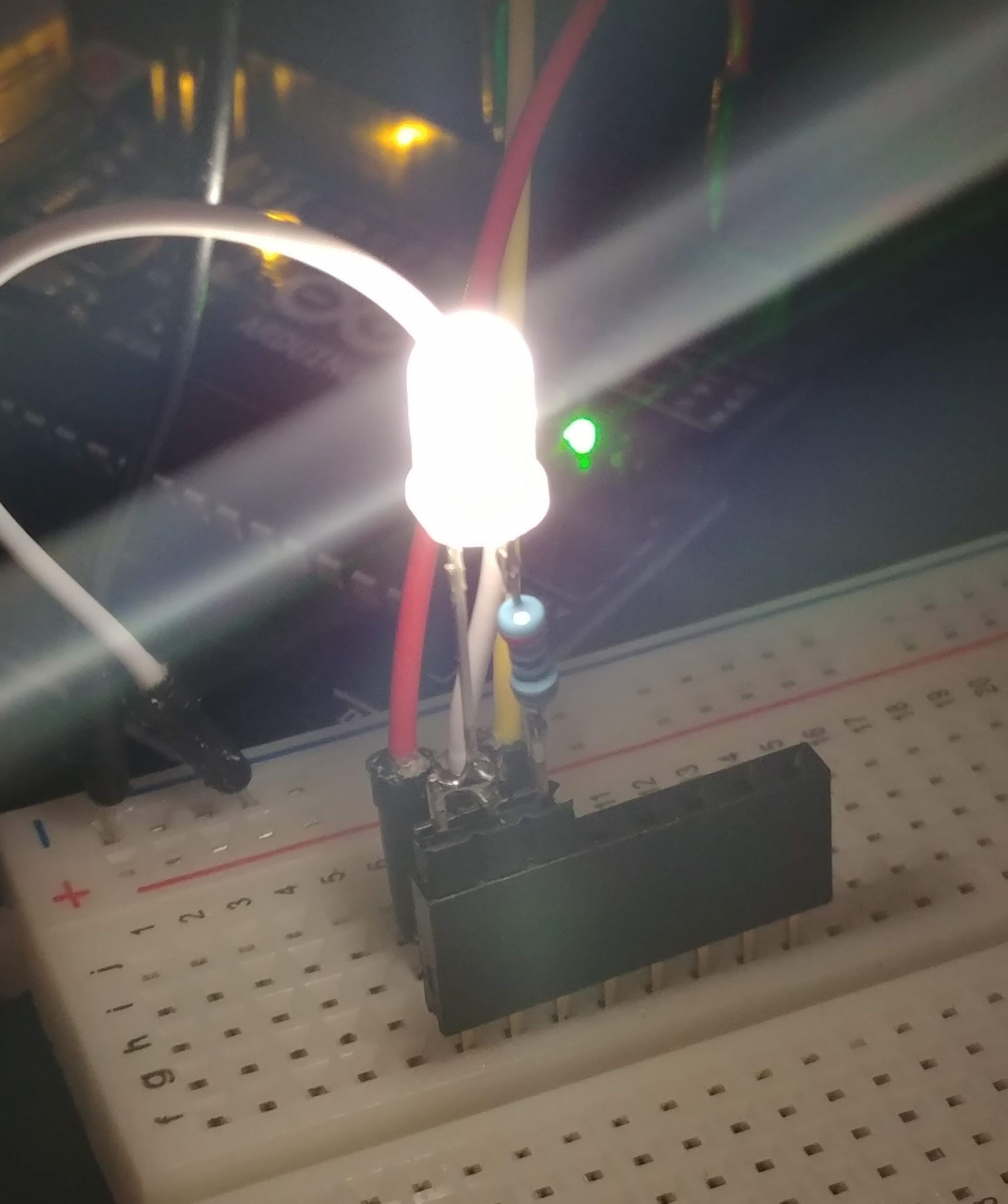
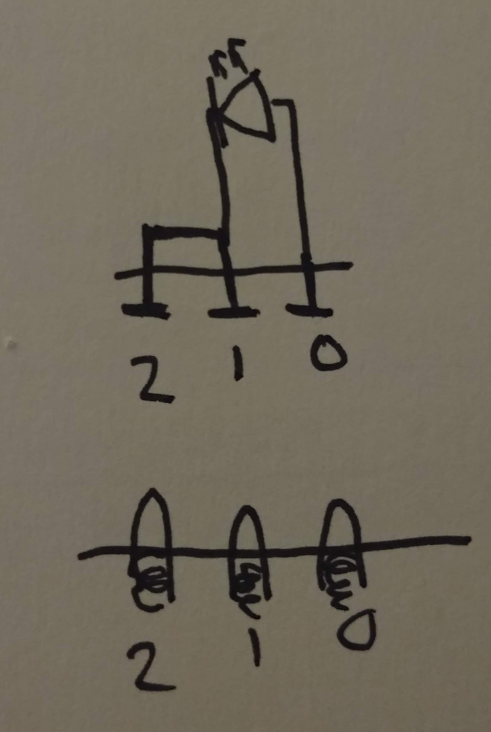
• All-in-one prototype

    Grant Stankaitis01/24/2020 at 06:33 0 comments

    So much has happened since the last log!

    In this log, I'm documenting the steps I took to assemble everything into one piece with the heart prototype. As you can see in the video below, all 4 LEDs are currently working and the Arduino is still able to sense when everything is connected up!

    I assembled it all with a MetroMini and the DFPlayer on a breadboard on the back of the heart. I connected wires to each of the pogo pins and wired them to the MetroMini. I chose the MetroMini because it uses the ATMega328P microcontroller, the same found in the Arduino Uno but in the surface mount package. I've worked out a few bugs in the code, so now I feel pretty confident and satisfied with the functionality. I'm also very happy with the size of the package and it's exciting to see it all contained in one piece!

    The next step is converting this to a schematic and PCB layout, which will give me a consistent foundation to build on. I've learned how to build a 'barebones Arduino' using the ATMega328P 28-pin DIP package, so that's what you'll be seeing in the next update!

  • Sound test

    Grant Stankaitis12/29/2019 at 02:08 0 comments

    After I mocked up and printed out the remaining heart pieces, I moved on to working on the sound.

    The sound for the Healing Heart is supposed to play when all 4 pieces are connected. As you can see from the video, when the 4th piece snaps in, the heart plays a sound! I picked a random sound clip that I had lying around on my computer.

    The sound is played through a DFPlayer Mini and a MicroSD card that contains a sound file. At this point, I chose to use a DFPlayer Mini because of the convenience of using a MicroSD card. For the final versions of the Healing Heart, I will implement storage with some sort of flash memory that is much more efficient and compact.

    When the Arduino detects that all 4 LEDs are connected, it sends a serial command (via SoftwareSerial) to the DFPlayer to play the sound file on the SD card. This allows the Arduino to offload the playback to the DFPlayer so it can continue running the main loop, thus allowing the Arduino to continue to switch the power on/off to the LED pins if a piece is disconnected while sound is playing.

    I believe this is an effective way to implement sound playback because the sound playback doesn't take up the processing power/time of the microcontroller (microcontroller doesn't freeze and wait for sound to finish). It is instead offloaded to a separate processing element that decodes the serial command and handles audio playback.

  • First heart piece test!

    Grant Stankaitis10/31/2019 at 20:38 0 comments

    After printing and assembling the heart base, I had to figure out the best way to line up the heart pieces. I decided to make a little divider for the interior of the heart to help separate the pieces. Now, each piece has its own little recess to fit into!

    The blue piece is the heart piece that I modeled and printed. There are two little nubs coming off the top to allow you to grip the piece and remove it. The grey tape is to cover the magnets and hold them better in place. The magnets line up perfectly with the magnets in the heart base! The LED in the middle of the piece has an extrusion coming off the top to hold the spring contacts in place. I put a dab on hot glue on top of the contacts to hold them in place.

    I found these super awesome LEDs from Lighthouse LEDs that include resistors in the LED!!! Using these will save space by removing the need for a resistor on the anode leg of the LED. I think they lend to a much cleaner, simpler design as well.

    When powered up, the pins make proper contact with the spring contacts and the LED lights up!

    This is the best part of the whole thing. The magnets perfectly align the heart piece in the base! If the piece is not quite lined up, the magnets will snap the piece into place. I made sure to sufficiently distance the magnets in the base and the piece. There's enough force between the magnets to secure the piece, yet make it easy to remove the piece.

    Now that I have the first piece printed out and tested, I would like to slightly change the location of the magnets in the base/pieces.

    My next step will be modeling and printing out the rest of the pieces, so stay tuned!

  • Modified heart base

    Grant Stankaitis10/31/2019 at 20:10 0 comments

    After my assembling my first iteration of the heart base, a few issues surfaced.

    1. The perf board was raised above the rest of the heart base. I decided it was a much better idea to recess the perf board into the base so that the top sits flush with the rest of the base.
    2. In order to test the fitment of the heart pieces, the heart base needed to have some kind of wall around the outside. So, I put a small lip around the outside for the pieces to have a place to drop in!
    3. I made the slots for the underside of the pins larger to make it easier to solder to the pins.
    4. Probably a few other minor tweaks that I can't remember.
    Updated heart base with changes implemented

    Along with the heart base, I soldered an LED to the pin contacts to test the connection. In this picture you can also see the raised lip and recessed perf  board.

    Exciting things are coming in the next log!!!

  • Pogo pins, perf board, and 3D printed prototype

    Grant Stankaitis10/31/2019 at 19:59 0 comments

    I began to assemble the first prototype! My goal was to place 3 pogo pins on the farthest corners of the perf board to make it easier to line up the pieces of the heart with the pins. As you can see, I soldered the pogo pins through the board, with the other side connecting to the appropriate Arduino pins. I modeled and 3D printed every piece in this project. I am a very hands-on person, so being able to quickly print out a test part is incredibly useful!

    I spent a lot of time in Inventor modeling the heart base and making sure my measurements of the perf board were correct. Hopefully since I triple checked everything, the pins should line up with the pieces! Since this is a preliminary test, I decided to keep it simple and make the base relatively flat and quick to 3D print. In the final versions, the heart will look more like the 3D heart on the home page of this project.

    I secured the perf board and the pins in place with hot glue. I had issues with the copper traces breaking off of the other side of the perf board (cheap perf board ugh).

    Here you can see the base holding the perf board in place:

    Here is the underside of the heart base. There's 8 cavities carved into the bottom. These cavities are meant to hold magnets. There will be 2 magnets for each section, which will help guide/align the corresponding heart piece. The magnets also serve to provide enough force to activate the pogo pins when the heart piece is placed down.

    There are also 4 slots extruded through the base to allow the pogo pins to be connected through the bottom. I slightly misaligned these slots, so my next iteration will fix that issue.

  • Hot-swappable LED test

    Grant Stankaitis10/14/2019 at 07:06 0 comments

    The hot-swappable LEDs work!

    I breadboarded up my concept and wrote a simple program to turn on a red LED when it senses that all 4 LEDs are connected. You can see the red LED turn on and off when I connect and disconnect the 4th LED. Pretty awesome first step!

  • Hot-swappable LED proof of concept

    Grant Stankaitis10/08/2019 at 05:49 0 comments

    I breadboarded my hot-swappable LED concept that I outlined in the last post. I attached an LED to male header pins and wired my Arduino up to a female header. I was able to remove insert and remove the LED to simulate fitting a heart piece into the base. This works surprisingly well, so I'm excited to implement it with pogo pins on a PCB! I have sourced 5V leds with built-in internal resistors, so this will eliminate the need for an in-line resistor with the LED, reducing the bulkiness of the design.
    Crude soldering to header pins
    LED lit up!!!

  • Project thoughts

    Grant Stankaitis10/08/2019 at 05:38 0 comments

    The goal of this project is to use pogo pins (spring-loaded contact pins) connected to an Arduino to power the LEDs in the heart pieces.

    There will be two main pieces to the project: the heart base and the removable heart pieces that connect into the base. The heart pieces will connect into the base, and using pogo pins to account for play, the LED will be lit to indicate successful placement of a piece. I borrowed this concept from magnetic connectors that are used to charge devices like smart watches, where the magnets guide the pins to their connection points and keep the connector secured.

    The large heart pieces will have 2 magnets per piece, with two matching magnets in the base. This will allow the heart pieces to be secured into the base without fine motor skills, which young children may lack. It will be similar to placing a toy block into its respective shaped hole.

    Each heart piece will house an LED, and upon being placed, the LED will light up. To connect the LED to the power/the Arduino, the LED will use contact pads located on the bottom of the heart piece. The contact pads will mate with the corresponding contact pads in the heart base.

    There will be 3 pins per LED. Pin 0 will be connected to a digital output pin, which will send a HIGH value to light up the LED. Pin 1 will be connected to ground. Pin 2 will be connected to a digital input pin.

    Pin 0 is connected to a digital output pin to allow the microcontroller to send HIGH/LOW values. HIGH will be sent when a connection is detected, and LOW will be sent when the connection is broken. Pin 2 will be acting as the switching mechanism to send these values. I decided to implement it this way to make it safer for children to happen. Even though it is only 5V, it's probably a better idea to have a disconnected circuit if children start poking around with the pins.

    Pin 1 will be the ground pin. This serves as the ground for both the LED circuit and the switching mechanism.

    Pin 2 is connected to a digital input pin to allow the microcontroller to detect a connection to an LED. I borrowed this concept from a recent project, where I wired a physical switch to ground and a digital input pin. When a connection is detected (circuit completed), then the microcontroller will send a HIGH value to Pin 0 to power on the LED. When disconnected, a LOW value is sent. It is important that I am using an extra pin here (as opposed to a standard 2 pin setup to power an LED) because this will allow the microcontroller to count the amount of LEDs that are connected. Once all 4 heart pieces are put in place (all 4 LEDs connected), a sound will be played to indicate that the children have completed the puzzle correctly.