 HummusPrince
This project has mainly an educational purpose, in which I learn many new skills. These are described more elaborately in the logs, where also most of the progress will be recorded.
Currently done:
- Being able to program the MCU.
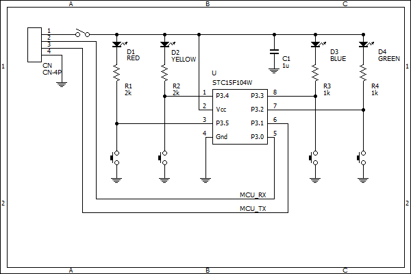
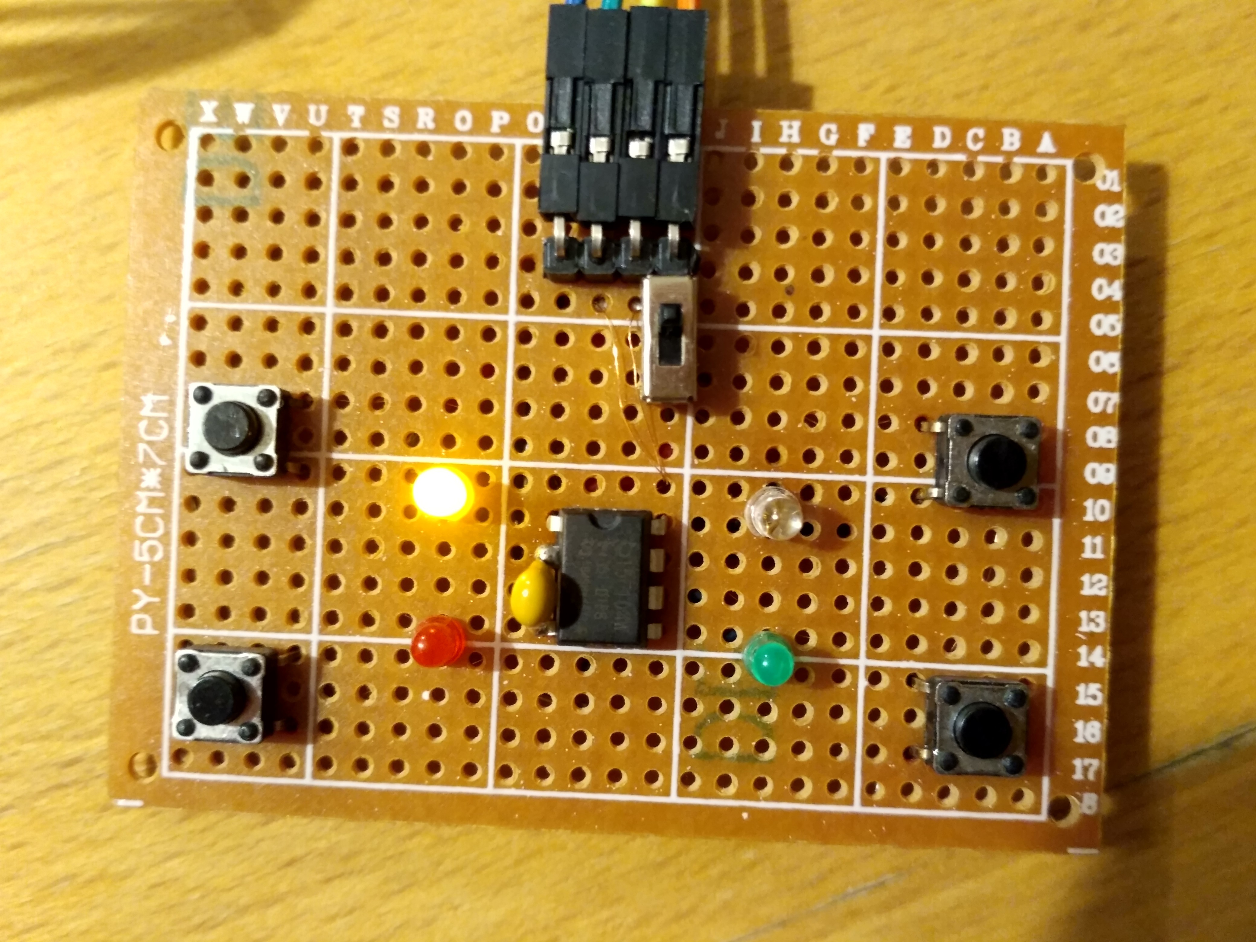
- Build the game's hardware.
- Learn how to use the toolchain.
- Write the game logic.
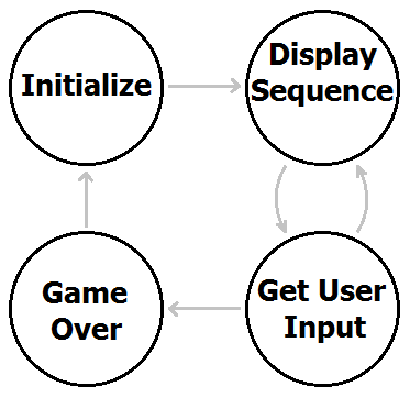
- A rewrite of Semyon's code, using byte operations this time and timer interrupts rather than loops.
Currently I have a working game, which is moderately entertaining to play. This is the main milestone I've marked for myself.
So what now? Here are a few ideas which might or might not see daylight:
- Beautify the game to make it more attractive and fun to play, by e.g. PWM the LEDs to get 'soft' light and fade effects.
- Add a speaker - add sound to this thing.
- Add features such as high-score counter, fun game-over animation etc.
- Make a proper PCB.
- Write additional games to this thing, such as a basic Whac-A-Mole clone.
Additional ideas are welcomed.
 Keith
Keith
 kodera2t
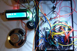
 Ken Yap
 David P Smith
When your passion becomes a profession, you learn things doing your project. I have been assigned a project like this and I had no idea how to do it successfully. It is great to know how to learn things from the projects that you are doing. Well, I have written a motivating essay for the programmers with the help of essaywritingservice which I hired after reading reviews about it at EduBirdie source because I was told that it is the only source that shares real reviews of the people with us.