 HummusPrince
So after having a working version of Semyon I wanted to familiarize myself with use of the special hardware present in the device. That is, timers, external interrupts, and special power modes.
Timers
So the STC15F104W has 2 timers, called T0 and T2.
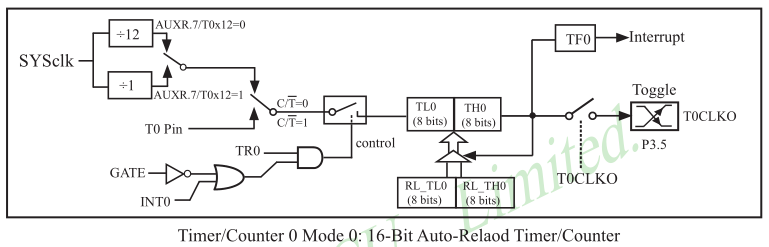
T0 is really a 16 bit auto-reload timer. One can disable auto-reload or use other timer modes like the 8051 traditional 8-bit auto-reload timer. The traditional control bits for the timer exist.
T2 is a skinnier version, only functioning as a 16 bit auto-reload timer. It is totally non-compatible with T2 present in the 8052 MCU, and has no bit controls - one has to fiddle with the whole control registers themselves.
None of these has a prescaler except for the 12 clock prescaler for legacy support, which is kinda lame. However, given the auto-reload feature, one can easily use overflow interrupts to get that exact functionality without giving up any clock cycle precision.
The first target for changes was the delay calls. The DJNZ loops are simple but this is a classic place to use a timer at. The delay functions now looked thus:
delay_debounce:
    mov r7, #0x01
    sjmp delay_loop

delay_display2:
    mov r7, #0x05
    sjmp delay_loop

delay_display:
    mov r7, #0x16

delay_loop:
    mov TL0, #0x00
    mov TH0, #0xc0
    delay_loop_2:
        setb TR0
        jnb TF0, .
        clr TF0
        djnz r7, delay_loop_2
    clr TR0
    ret
This is really setting the timer, and continually polling it. The timer is set to initial value of 0xC000, which is effectively a 14-bit timer which overflows faster. The loop is repeated R7 times, and thus granularity is achieved.
The next victim must be the seed generation. As mentioned in previous logs, it incremented the LFSR, pooling user input in-between. Replacing it with a time is classic too:
initialize:
    ;This is the initialization phase of semyon.
    ;It should also generate the seed value for PRNG.
    mov V_LED_CNT, #1
    mov V_LED_MAX, #1
    mov TL0, #0x01
    mov TH0, #0x00
    mov TMOD, #0x00
    mov AUXR, #0x81
    setb TR0

    initialize_seed_loop:
        mov a, P3
        orl a, #P_LED_ALL
        cjne a, #0xff, initialize_ret
        sjmp initialize_seed_loop

    initialize_ret:
        mov a, P3
        orl a, #P_LED_ALL
        cpl a
        cjne a, #0x00, initialize_ret

    clr TR0
    clr TF0
    mov V_SEED_L, TL0
    mov V_SEED_H, TH0
    lcall delay_display
    mov V_STATE, #S_DISPLAY_SEQUENCE
    ret
That is lots of timer configurations, then enableing the counter and polling user input, then waiting for user to release the buttons, and using the timer value as the seed.
This makes the seed to increment about 47 times faster. It is almost feasible to use a 24-bit LFSR!
External interrupts
In STC15 family there are 5 external interrupts - the traditional INT0 and INT1, and INT2, INT3 and INT4 which are only falling edge activated. In STC15F104W, P3.2 to P3.5 are mapped to INT0 to INT3 respectively, which means they can be used to get user input.
So I declared the relevant interrupt vectors:
.org 0x0003     ;ext0
_int_GLED:
    mov V_INTERRUPT_LED, #P_N_LED_G
    ljmp ext_interrupt_handler


.org 0x0013     ;ext1
_int_BLED:
    mov V_INTERRUPT_LED, #P_N_LED_B
    ljmp ext_interrupt_handler


.org 0x0053     ;ext2
_int_YLED:
    mov V_INTERRUPT_LED, #P_N_LED_Y
    ljmp ext_interrupt_handler


.org 0x005b     ;ext3
_int_RLED:
    mov V_INTERRUPT_LED, #P_N_LED_R
    ljmp ext_interrupt_handler
V_INTERRUPT_LED is a new variable I declared to store a value indicating which button was pressed, and is used in the game logic akin to the way the polled P3 value was used.
All these external interrupts jump to the same handler, which disables the external interrupts:
ext_interrupt_handler:
    anl AUXR2, #~0x30    ;EX3 | EX2
    anl IE, #~0x05        ;EX1 | EX0
    reti
Power and Clock Control
Waiting for external interrupts to happen using an idle loop that polls something still misses the point. What I really want is to enable external interrupts, and then halt the CPU until the interrupt happens.
There's a register that allows one to do it, called PCON.
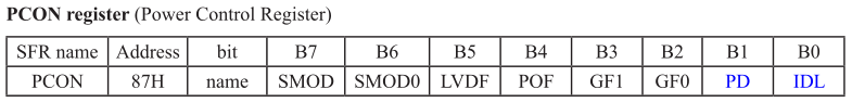
PD and IDL bits set the MCU to Power-Down and Idle modes, respectively.
In Idle mode, the CPU is shut down, but the rest of the hardware still function - that is all the peripherals, including timers, com. and ADCs. The CPU will wake up at any interrupt set to it.
In contrast, Power-Down mode shuts down the whole device, so it can only wake up in case of external interrupts.
Idle mode is what I wanted earlier - and it replaces the idle loops with much elegance.
ext_int_get_input_beginning:
    mov IE, #0x05    ;EX1 | EX0
    mov AUXR2, #0x30    ;EX3 | EX2
    setb EA

    orl PCON, #0x01     ;IDL

    clr EA
    ;Some debounce logic
For user input where no timer should run in the background, one can also go Power-Down altogether:
orl PCON, #0x02 ;PD = power down
In the delay routines, the IDL mode applies too.
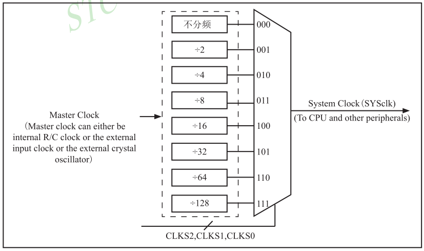
Moreover, one might want to slow down the whole system clock, as the timers can't be prescaled. This can work for the delays as no computations are required to be made when delay is called.
Prescaling is done using the PCON2 register (also called CLK_DIV) which is specific to STC MCUs. It's 3 LSBs control a system clock divider up to 128.
Using the divider and idle mode make the delay much more elegant, littered only by SFR configuring:
delay_debounce:
    mov T2L, #0x00
    mov T2H, #0xfc
    sjmp delay_activate

delay_display2:
    mov T2L, #0x00
    mov T2H, #0xe0
    sjmp delay_activate

delay_display:
    mov T2L, #0x00
    mov T2H, #0xb0
    ;sjmp delay_activate

delay_activate:
    orl IE2, #0x04        ;Enable T2 interrupt
    orl AUXR, #0x04        ;T2 is 1clk
    orl PCON2, #0x07     ;clk/128
    setb EA

    orl AUXR, #0x10     ;enable T2
    orl PCON, #0x01     ;IDL
    anl AUXR, #~0x10     ;disable T2

    clr EA
    anl PCON2, #~0x07     ;clk/1
    ret
Know your hardware
I might be an extremist, but IMO the hardware and real-life events are the focus of embedded design, and the programming is only a tool to get there.
Thus, peripheral configuration and use is the essence of embedded programming. It is there where the slim line between programming and real-life is.
An embedded code which makes almost no use of the existing peripherals is really missing the point. E.g. writing code that wiggles GPIOs using digitalWrite() in arduino is not embedded code - the thought process is that of general purpose computer programming rather than a real-time/control mindset. Moreover I believe that one haven't really used an MCU until he activated some of it's hardware by tweaking the SFRs directly.
Even if I sound completely nuts, using the peripherals still has one good point - it is very educational for me. Using peripherals rather than funky code solutions is the right direction towards more complex projects which shall require peripheral use, say real-time control, which is very cool.
Discussions
Become a Hackaday.io Member
Create an account to leave a comment. Already have an account? Log In.