 HummusPrince
My name is Random, Pseudo Random
We need to create a random sequence to display to the player. Generating real random values for the LEDs is possible, though may be somewhat cumbersome as it means constantly generating random variables and storing them.
Moreover, it is probably unnecessary. This is just a game, not some crazy bitcoin e-wallet that depends on true randomness to securely store all your money or something.
Introducing pseudorandomness! We can generate a sequence that looks seemingly random to the unsuspecting eye, but is generated using some sort of deterministic algorithm.
Magical LFSRs
One such algorithm is called a Linear Feedback Shift Register, or LFSR in short. The idea is using a shift register of certain length, and shift in the XOR of several bits from the shift register itself (hence the feedback). These bits are usually referred to as the LFSR taps.
For an LFSR, initial state matters. All LFSRs output a constant stream of 0s when initially loaded with zeros. But when loaded with anything else, a sequence of 1s and 0s will flow out.
An LFSR is a finite automaton, thus can only output a finite stream of bits before it repeats itself. If the taps are chosen in a certain way, one can get the longest stream possible, which for an LFSR of n bits is 2^n - 1 states.
For further read, I can recommend the book 'mathematics - the man made universe' by Sherman k. Stein, whose 8th chapter offers a different look on the subject of such maximal bit sequences, concerning medieval indian poetry rhythms.
Are 16 bits enough?
Anyway, I've chosen to use an 16-bit LFSR, where each LED value is two consequent bits of the LFSR. It means that all the possibilities for the first 8 LEDs are possible (apart from 8 consecutive LEDS), but the ninth LED and beyond will be determined by these first 8 LEDs in a deterministic way.
How long will it take until the player would play the same game twice? According to the birthday paradox, after about 256 games there is a 50% probability that some games had identical sequences.
That result is good enough for me - I don't suspect that any user will play that many game and also remember the sequence behind that. Moreover, I personally get bored after 20 games at most, usually far less. So it must be fine I guess.
Comparing it to an 8 bit LFSR, the number of possible sequences is 256. The player will begin to see repetitions after 16 games with 50% probability, which isn't that great. The game will probably begin to feel degenerated after 15 minutes of gameplay or so.
How it really look like
The LFSR I decided to implement looks thus:
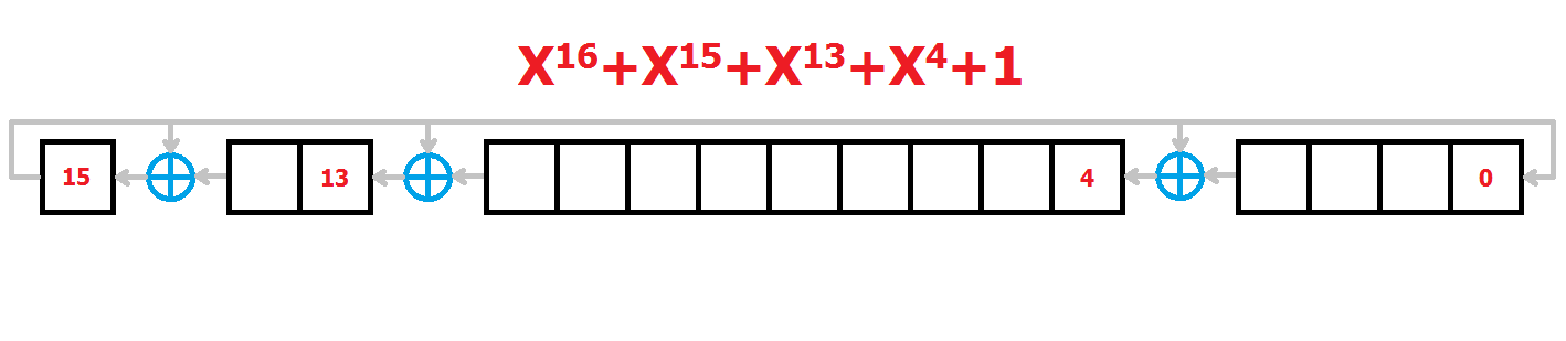
Notice that it's not what I have described before - this is a Galois LFSR, where the output get xored to multiple bits inside the shift register. I'll shortly explain why I chosen Galois LFSR, but for now it's enough to say that it's basic properties and behaviour remain the same.
The polynomial should be maximal to get a full sequence - I just took the polynomial from the table in the wikipedia article for LFSRs, and briefly made sure that it is indeed maximal by simple enumeration of the outputs.
This is how the nice picture translates into code:
inc_lfsr:
    ;Now with Galois LFSR of 16 bits with polynomial
    ;x^16 + x^15 + x^13 + x^4 + 1 (mask 0xa011)
    clr c
    mov a, r0
    rlc a
    mov r0, a
    mov a, r1
    rlc a
    mov r1, a
    jnc inc_lfsr_ret
    mov a, r0
    xrl a, #P_LFSRMASK_L
    mov r0, a
    mov a, r1
    xrl a, #P_LFSRMASK_H
    mov r1, a
inc_lfsr_ret:
    ret
There isn't that much to it. r0 and r1 are the low and high byte of the LFSR respectively (MSB of r1 is the feedback bit). The convenient way to shift them left as one long shift register is shifting each byte, using the C flag to hold the output of low byte and pass it to the higher byte.
After we shifted them all we're left with a feedback bit, now stored in the C flag. If C is 0, no action is needed and we immediately return. However if it is 1, the relevant mask must be xored to it.
The brancing itself is made using the JNC opcode, which is quite useful for multi-byte logic. The mask is stored as parameters which are used as immediate values.
If we want to make it a little bit prettier, and we use global variables anywhere (including registers), we can ditch some accumulator MOVs:
inc_lfsr:
    clr c
    mov a, r0
    rlc a
    mov r0, a
    mov a, r1
    rlc a
    mov r1, a
    jnc inc_lfsr_ret
    xrl 0x00, #P_LFSRMASK_L
    xrl 0x01, #P_LFSRMASK_H
inc_lfsr_ret:
    ret
Despite being elegant, notice the use of absolute IRAM addresses for r0 and r1 (0x00 and 0x01 respectively) - It might become a huge mess would I want to switch a register bank for example.
This code portrays very well why I wanted a Galois LFSR rather than the 'regular' Fibonacci one - picking bytes one by one and xoring them together is uglier and more tedious to write - and far less convenient to change the tap values for than xoring whole bytes with constant masks.
To get an LED color I'd simply call inc_lfsr twice:
get_led_color:
    ;Puts in r3 the value of the next LED to display.
    mov r3, #0
    lcall inc_lfsr
    jnc get_led_color_2
    inc r3
    inc r3
get_led_color_2:
    lcall inc_lfsr
    jnc get_led_color_ret
    inc r3
get_led_color_ret:
    ret
Random seed
The only catch is using a random seed, an initial value for the algorithm to use. Without it, Semyon will be a deterministic version of simon, which makes a very boring game. Trust me.
It means that I must have some source of randomness. One great such source is user input, or rather input timing. The player will never be able to click the buttons just at the same time since game over as in previous games - our clicking resolution is 10ms at best, while a counter can run as fast as the clock, around 100ns for instance. That's 5 orders of magnitude, plenty for random. This is stressing it out though - a standard user will take 1-2 seconds between games, as it looks to me.
Thus come initialization state of the game:
initialize:
    ;This is the initialization phase of semyon.
    ;It should also generate the seed value for PRNG.
    mov V_LED_CNT, #1
    mov V_LED_MAX, #1
    mov V_SEED_L, #0xff
    mov V_SEED_H, #0xff


    mov r0, V_SEED_L
    mov r1, V_SEED_H
    initialize_seed_loop:
        jnb RLED, initialize_ret
        jnb YLED, initialize_ret
        jnb GLED, initialize_ret
        jnb BLED, initialize_ret
        lcall inc_lfsr
        sjmp initialize_seed_loop

    initialize_ret:
    mov V_SEED_L, r0
    mov V_SEED_H, r1
    lcall delay_display
    mov V_STATE, #S_DISPLAY_SEQUENCE
    ret
Nothing fancy here. After initializing some important values, like 0xFFFF as initial LFSR value (just something that's not all zeros) I simply wait for the user to click any button. Until he clicks, I simply increment the LFSR periodically.
Let's see if it makes sense.
The MCU runs now with a clock of 11.0592MHz, that is 1.1E7 clocks a second approximately. There probably are ways which I don't know of to automatically count cycle duration of code, but for now let's count cycles manually.
According to the datasheet (page 340), One incrementation takes:
- 1 clock X 1 JNC
- 1 clock X 4 MOV A,Rn or vice verse
- 1 clock X 2 RLC
- 3 clocks X 2 XRL iram, #Immediate
- 3 clock X 1 JNC
- 4 clocks X 1 RET
- 5 clocks X 4 JNB
- 4 clocks X 1 LCALL
- 3 clocks X 1 SJMP
Total of 47 clocks. Given 65535 period of the LFSR, one should get:
Given that after losing the user will probably take more than 1 second to start a new game, this way to update the LFSR should span the whole seed-value range very well, with uniform-enough probability to get each seed. I'll call it random!
User input and debouncing
I always hate this part of such projects. If you never used them yet, know that tactile buttons are not very reliable - the physical contact tend to jump and vibrate, which can generate multiple click signals for the MCU input.
One way to solve it is connecting capacitors in parallel to the buttons and call it a day - they will low-pass-filter any pesky button bounce.
It makes sense when using discrete logic, but that's just lame when one has a full MCU to solve his problems. Thus I pulled out the vanilla way to debounce, which is simply adding delays.
I'm not proud of code you're about to see. Have a look:
poll_user_input_debounce:
    jnb RLED, poll_user_input_debounce_r
    jnb YLED, poll_user_input_debounce_y
    jnb GLED, poll_user_input_debounce_g
    jnb BLED, poll_user_input_debounce_b
    sjmp poll_user_input_debounce
    poll_user_input_debounce_r:
        lcall delay_debounce
        jb RLED, poll_user_input_debounce
        mov a, #0x00
        sjmp poll_user_input_debounce_delay
    poll_user_input_debounce_y:
        lcall delay_debounce
        jb YLED, poll_user_input_debounce
        mov a, #0x01
        sjmp poll_user_input_debounce_delay
    poll_user_input_debounce_g:
        lcall delay_debounce
        jb GLED, poll_user_input_debounce
        mov a, #0x02
        sjmp poll_user_input_debounce_delay
    poll_user_input_debounce_b:
        lcall delay_debounce
        jb BLED, poll_user_input_debounce
        mov a, #0x03
        ;sjmp poll_user_input_debounce_delay

    poll_user_input_debounce_delay:
    lcall delay_debounce
    jnb RLED, poll_user_input_debounce_delay
    jnb YLED, poll_user_input_debounce_delay
    jnb GLED, poll_user_input_debounce_delay
    jnb BLED, poll_user_input_debounce_delay
    ret
At first I simply wait for some button to be clicked == become low. If one is clicked, I wait for it as much as the delay_debounce routine takes, and if the button is still being held I return it's corresponding value. before the RET itself I debounce the part of leaving the button, which is probably redundant and unnecessary, but whatever.
One can also notice that this routine is an ugly m*thaf*cka - I wanted to maximize the use of bit opcode in this project, as these are quite new to me, but it turns out that the code will be much, much more compact and sensible by simply editing the P3 SFR instead.
Additionally, though it doesn't matter for this project, conditional jumps on bits e.g. JNB take as many clock cycles as more complex comparisons such as CJNE. This makes bitwise GPIO addressing quite pointless in my eyes.
This is a lesson learned - Bit operations are worth using only in specialized cases which deserve it. It might be a time-sensitive operations regarding a port e.g. bitbanging some serial protocol, or when extensive single bit calculations are required, to name a few I can think of. One exception to this: operations on the C flag are still very useful for multi-byte arithmetic and logic.
Last note about that - the code came out like some nasty version of arduino code, using these digitalRead wraps that work on one bit of the GPIO port registers at a time. I don't like using the arduino, somewhat for the lack of elegance and compactness of exactly such situations - Now doing so in 8051 assembly feels sevenfold worse and ugly.
But this thing works, anyway.
Game over
Nothing fancy - I just wanted all the LEDs to light together:
game_over:
    lcall delay_display
    clr RLED
    clr YLED
    clr GLED
    clr BLED
    lcall delay_display
    setb RLED
    setb YLED
    setb GLED
    setb BLED
    lcall delay_display
    lcall delay_display
    lcall delay_display
    mov V_STATE, #S_INITIALIZE
    ret
Nothing to behold. The clumsy use of bit operations once again shows that it wasn't a good idea to work that way. Here's a hypothetical way to make it much better by using regular byte operations:
P_LEDS_ALL = 0x3c

game_over:
    lcall delay_display
    xrl P3, #P_LEDS_ALL
    lcall delay_display
    xrl P3, #P_LEDS_ALL
    lcall delay_game_over
    mov V_STATE, #S_INITIALIZE
    ret
Isn't it better?
That's the code basically. These two logs got mush longer than I expected.
Anyway as mentioned earlier, the whole code can be found in the git repository.
For me, this preliminary version of Semyon was very educating, and I hope it was for you too :)
Discussions
Become a Hackaday.io Member
Create an account to leave a comment. Already have an account? Log In.