 Alexander Krause
current state of implementation:
- stack: CiA for ATcan* devices - 100% (done)
- stack: extensions for MCP - 0% (not started)
- user-software: monitor for CiA messages (done, python commandline tool)
- firmware: bootloader - 100% (done)
- user-software: bootloader - 100% (done, python commandline tool)
- PDO-functions: 100% (done)
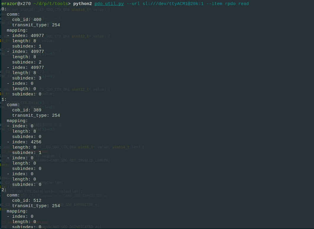
- user-software: pdo tool - 100% (done, python commandline tool)
- SDO-functions: 100% (done)
- user-software: pdo tool - 100% (done, python commandline tool)
- SDO- bindings: 100% (done)
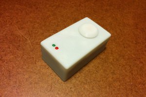
So what's missing? I'm currently working on some hardware and firmware for CiA. On my list are typical components for home-automation:
- relais-module with digital inputs and buttons (80% done, prototype exists)
- shutter-module with display and manual override (5% done)
- heating-actuator controler with manual override and LEDs (5% done)

 achan1989
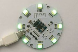
 deqing
 Owl Labs