 Ali
AliAim
The aim of this project is to design and construct an open-source pump for beverage dispensers that can also be remotely operated to reduce manual work needed by user.
Objectives
- Select suitable pump type.
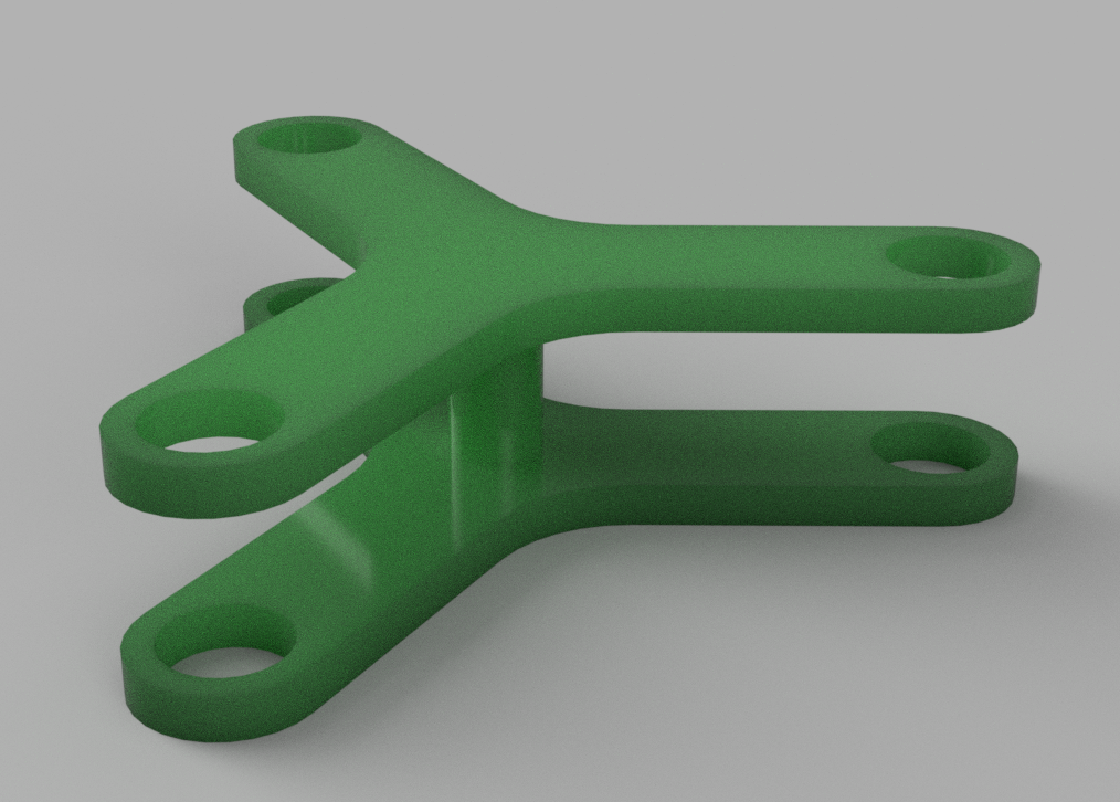
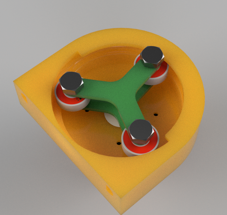
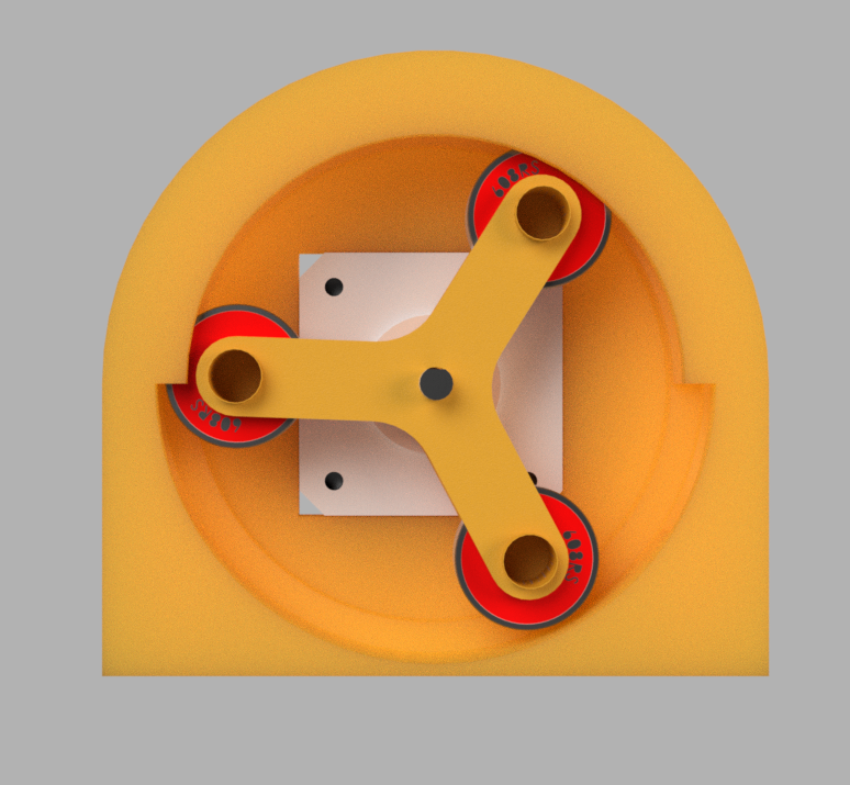
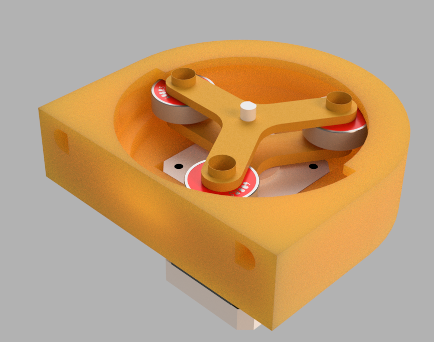
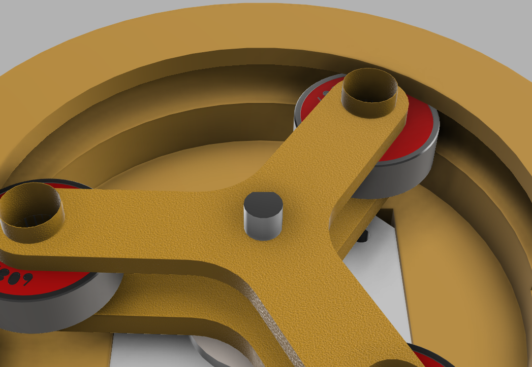
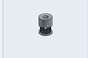
- Design pump sketches and 3D drawings.
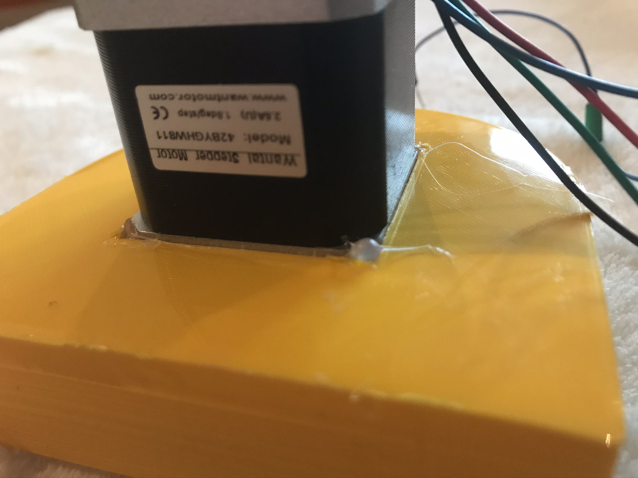
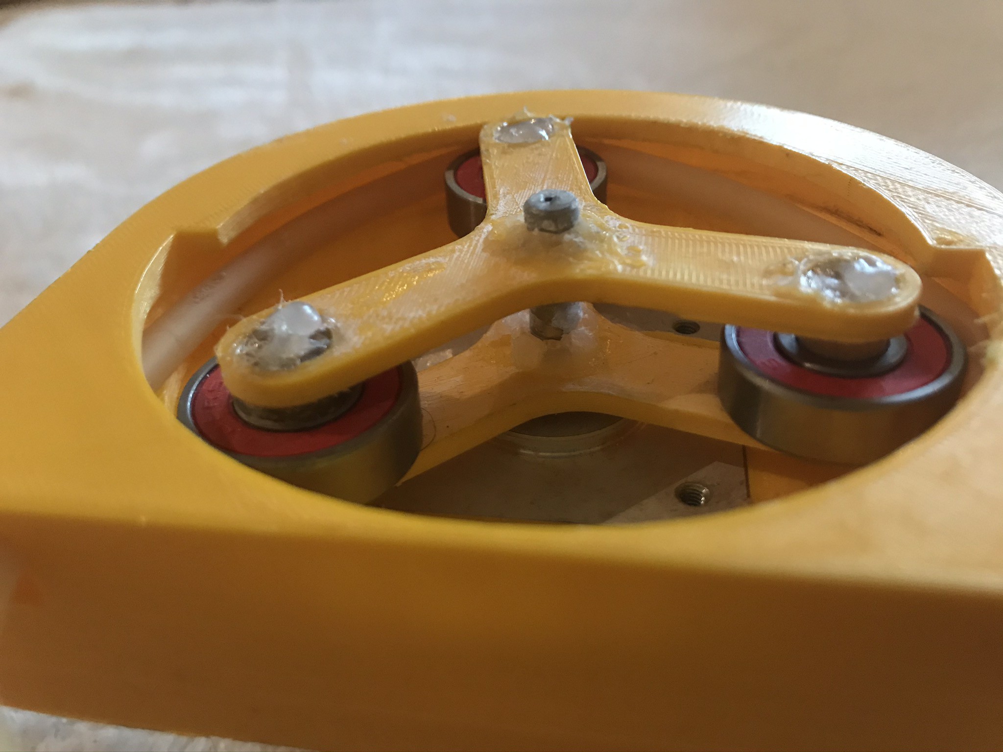
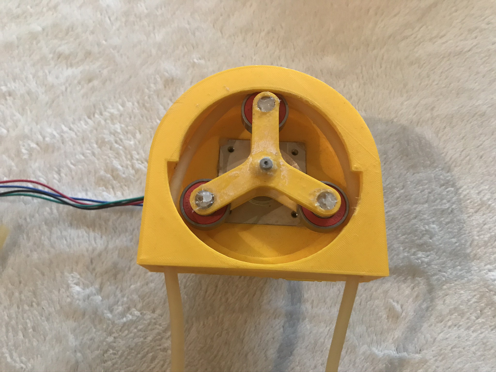
- Construct Prototype for testing.
- Test Prototype to identify any limitations and potential improvements.
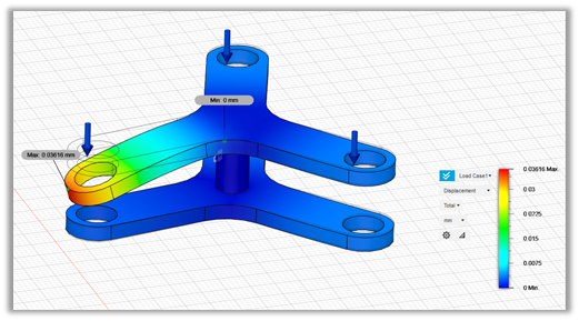
- Optimise design using analysis of prototype.
- Construct pump base upon final design changes.
- Install and connect micro-controller to allow for remote operation.
- Test Pump to ensure the full desired functionality is available.


 Michael Sinitsin
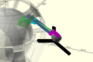
 DrYerzinia
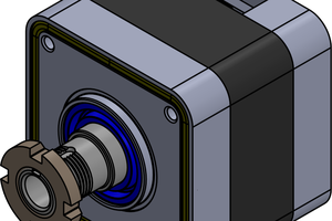
 J. M. Hopkins
I made a project with stepper motors before. I would suggest you try some open-source codes that can save you time and effort.