 Ali
AliAn estimate of the flow rate of the pump can be approximated from the rotational speed of the rotors and the cross-sectional area of the tubing. The flow rate is dependent on the fluid’s viscosity, tubing inner diameter, and backpressure. Therefore, the flow rate was calculated for a low viscosity Newtonian fluid in a pump setup with negligible back pressure or fluid elevation. The rotor is designed to compress the tubing to a distance of 2mm between the rotor’s tip and the wall of the raceway. Since the thickness of the tubing is 1mm, it is assumed that, at the point of compression, the tube walls are in complete contact and seal off the fluid. This means that no fluid is leaked backwards towards the inlet and that the rotor moves a fixed volume of fluid contained in the tubing. The total volume displaced in one revolution was be obtained:
Volume per revolution = 0.000916 Litres
RPM for 1.5 L/min = 1637
Torque at maximum speed = 1.4N.cm
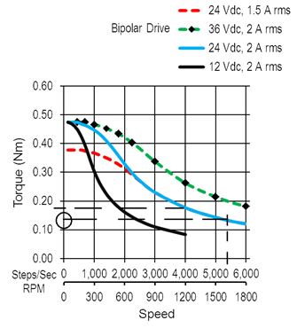
The output torque of the motor was obtained using the motor’s torque-speed curve shown in the curve above. The output value of the torque was found to be about 1.4N.cm which is smaller than the required torque. Therefore, the pump will not be able to operate at such high speeds with the proposed setup. The pump’s maximum operating speed is approximately 1200rpm which will result in a pump flow rate of around 1.1 L/min instead of 1.5 L/min.
Discussions
Become a Hackaday.io Member
Create an account to leave a comment. Already have an account? Log In.